7-2-8. Compressor Operation Output
Mode name : TCB-PCIN4UL
Operation
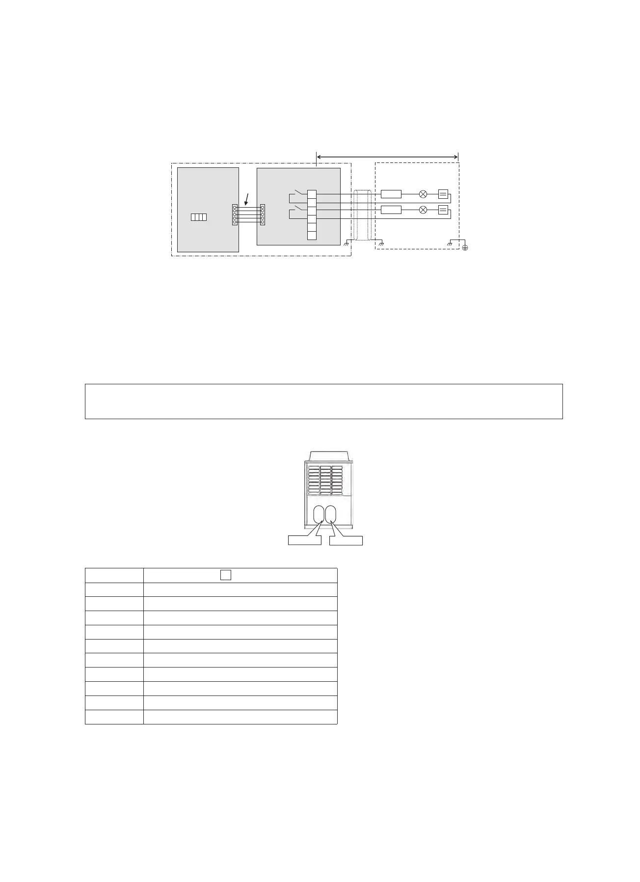
When a compressor is in operation, a relay connected to the output terminal assigned to it is turned on (closed).
When it is at rest, the relay is turned off (open).
The output terminals are named OUTPUT1 and OUTPUT2 from left to right when facing the front of the outdoor
unit, as shown in the diagram.
Note 1: Output Relay (K1, K2) Contact Specifications
• Please insert the following electrical rating to output terminals(Output1,2).
• When connecting a conductive load (e.g. relay coil) to loads K1and K2 insert a surge killer CR (for an AC
power supply) or a diode for preventing back electromotive force (for a DC power supply) on the bypass circuit.
<Electrical Rating>
200-240 VAC, 10 mA or more, 1A or less (non-conductive load)
24 VDC, 10 mA or more, 1 A or less (non-conductive load)
1 2
OUTPUT1
OUTPUT2
Model featuring
two compressors
Locally procured
Outdoor unit
Optional PCB
(See “NOTE”)
TB1
C2
L1 PS
1
CTR1
K1
OUTPUT1
2
L2 PS
SW16
3
CTR2
CN514
PJ20
K2
OUTPUT2
4
1234
5
6
Outdoor unit
interface PCB
ON
OFF
Shield
wire
C2
Connector cable 2 ( 2 )
CN514
Connector on interface side (green)
CTR1
Elapsed operation counter 1
CTR2
Elapsed operation counter 2
K1, K2
Relays
L1, L2
Operation indication LEDs
OUTPUT1
Compressor 1 operation output terminal
OUTPUT2
Compressor 2 operation output terminal
PJ20
Connector on optional PCB side
PS
Power supply unit
TB1
Terminal block
− 75 −
 Loading...