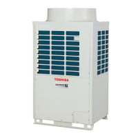
3. TERMINAL-PW (TB03)
1 Detachment
1) Perform work of procedure 1. of 1 Detachment . (Electric parts cover)
2) Remove the wires from the TERMINAL-PW (TB03).
3) Take off screws fixing the TERMINAL-PW (TB03). (φ4 x 0.6" (14mm), 2 pcs)
2 Attachment
1) Fix the terminal assembly as before.
2) Fit the fixing screws (φ4 x 0.6" (14mm), 2 pcs).
3) Connect the wires disconnected as before.
4) Attach the Electric parts cover. (Refer to 1. of 2 Attachment)
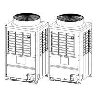
4. TERMINAL-2P (TB01, TB02)
1 Detachment
1) Perform work of procedure 1. of 1 Detachment .
(Electric parts cover)
2) Remove the wires from the TERMINAL (TB01 and TB02).
3) Take off the screws fixing the TERMINAL (TB01 and TB02).
(φ4 x 0.6" (14mm), 1pc)
2 Attachment
1) Fix the terminal assembly as before.
2) Fit the screws (φ4 x 0.6" (14mm), 1 pc)
3) Connect the wires disconnected as before.
Fit the cylindrical protrusion of the terminal block (TB01 and TB02)
into the hole of the sheet metal of the electrical box.
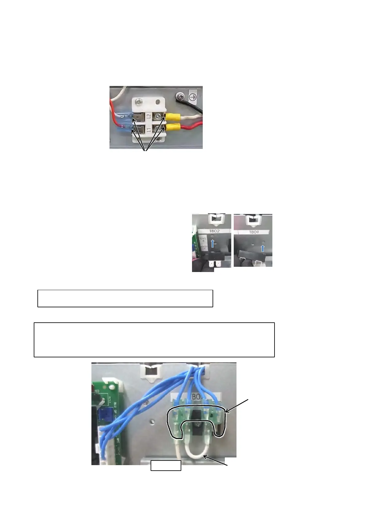
[RBM-Y0384FUL]
(Refer to fig.A) For the leads of the coil (5pcs) that has the faston terminal of the flag type on the edge
(one side) and the lead (1pc) that has the faston terminal of the flag type on the both ends, connect them
to the TERMINAL (TB01). (Refer to fig.A) For the connection direction to the TERMINAL (TB01) for the
lead that has the faston terminal of the flag type , refer to the figure A.
 Loading...