– 110 –
No. Function
Outdoor unit
for control
P.C. board
connection
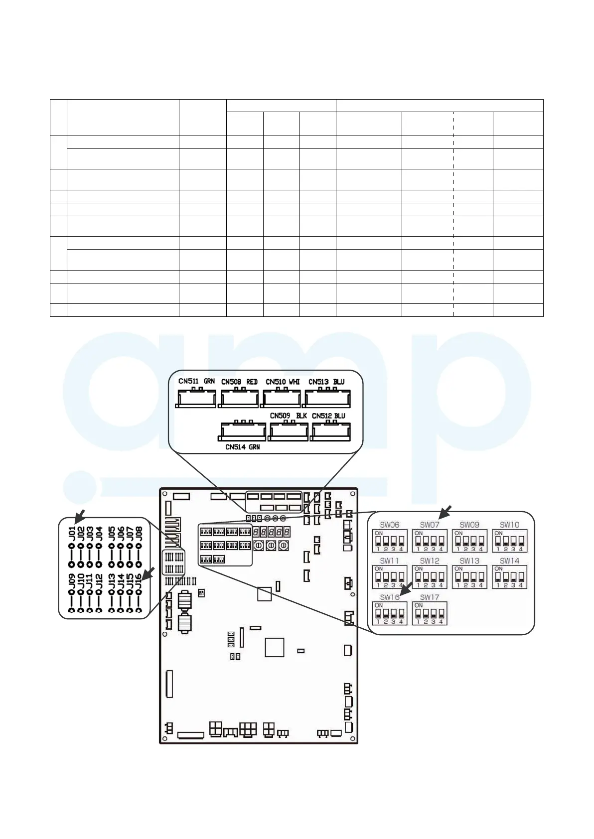
Control P.C. board to be used Outdoor unit interface P.C. board setting*
PCDM4E PCMO4E PCIN4E Connector No. DIP SW No. Bit
Jumper to be
removed
1
Power peak-cut Control (Standard) Header unit √ – – CN513(blue) SW07 1 –
Power peak-cut Control (For one
input function)
Header unit √ – – CN513(blue) SW07 1 J16
2
Power peak-cut Control (Enhanced
Functions)
Header unit √ – – CN513(blue) SW07 1.2 –
3 Snowfall Fan Control Header unit – √ – CN509(black) – – –
4 External master ON/OFF Control Header unit – √ – CN512(blue) – – –
5
Night operation (sound reduction)
Control
Header unit – √ – CN508(red) – – –
6
Operation Mode Selection Control Header unit – √ – CN510(white) – – –
Operation Mode Selection Control
(forced choice)
Header unit – √ – CN510(white) – – J01
7 Error/Operation output Header unit – – √ CN511(green) – – –
8 Compressor Operation Output
Individual
outdoor unit
––√ CN514(green) – – –
9 Operating Rate Output Header unit – – √ CN514(green) SW16 1 –
Connector layout
DIP switch layout
Interface P.C. Board
Jumper wire layout
6-8. Applied Control Using Optional Board for Outdoor Unit
Optional control P.C. boards provide access to a range of functions as listed below.
Layout of Outdoor Unit Interface P.C. Board
* DIP switch settings and jumper wire statuses vary from function to function.
www.ampair.co.uk | sales@ampair.co.uk
 Loading...