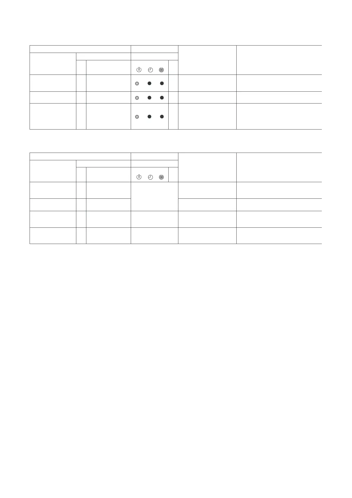
Check code
Display of receiving unit
Typical fault site Description of trouble
Outdoor 7-segment display Indicator light block
Sub-code
Flash
E01 – –
No master remote control,
failure remote control
communication (reception)
Signals cannot be received from indoor unit;
master remote controller has not been set
(including two remote controller control).
E02 – –
Failure remote control
communication (transmission)
Signals cannot be transmitted to indoor unit.
E09 – –
Duplicated master remote
control
Both remote controllers have been set as
master remote controller in two remote
controller control (alarm and shutdown for
header unit and continued operation for
follower unit)
Operation
Timer Ready
Remote control
Check code
Display of receiving unit
Typical fault site Description of trouble
Central control
Outdoor 7-segment display Indicator light block
Sub-code
Flash
C05 – –
No indication (when
main remote control
also in use)
Failure central control
communication (transmission)
Central control device is unable to transmit
signal due to duplication of central control
device
C06 – –
Failure central control
communication (reception)
Central control device is unable to receive
signal.
C12 – – –
Bracket alarm for general-
purpose device control
interface
Device connected to general-purpose
device control interface is failure.
As per alarm unit (see
above)
Group control follower unit
trouble
–P30 –
Group follower unit is troubled (unit No. and
above detail [ ∗∗∗ ] displayed on main remote
controller)
Operation
Timer Ready
(Check code detected by remote controller)
(Check code detected by central control device)
Note: The same trouble, e.g. a communication trouble, may result in the display of different check codes
depending on the device that detects it.
Moreover, check codes detected by the main remote controller/central control device do not necessarily
have a direct impact on air conditioner operation.
 Loading...