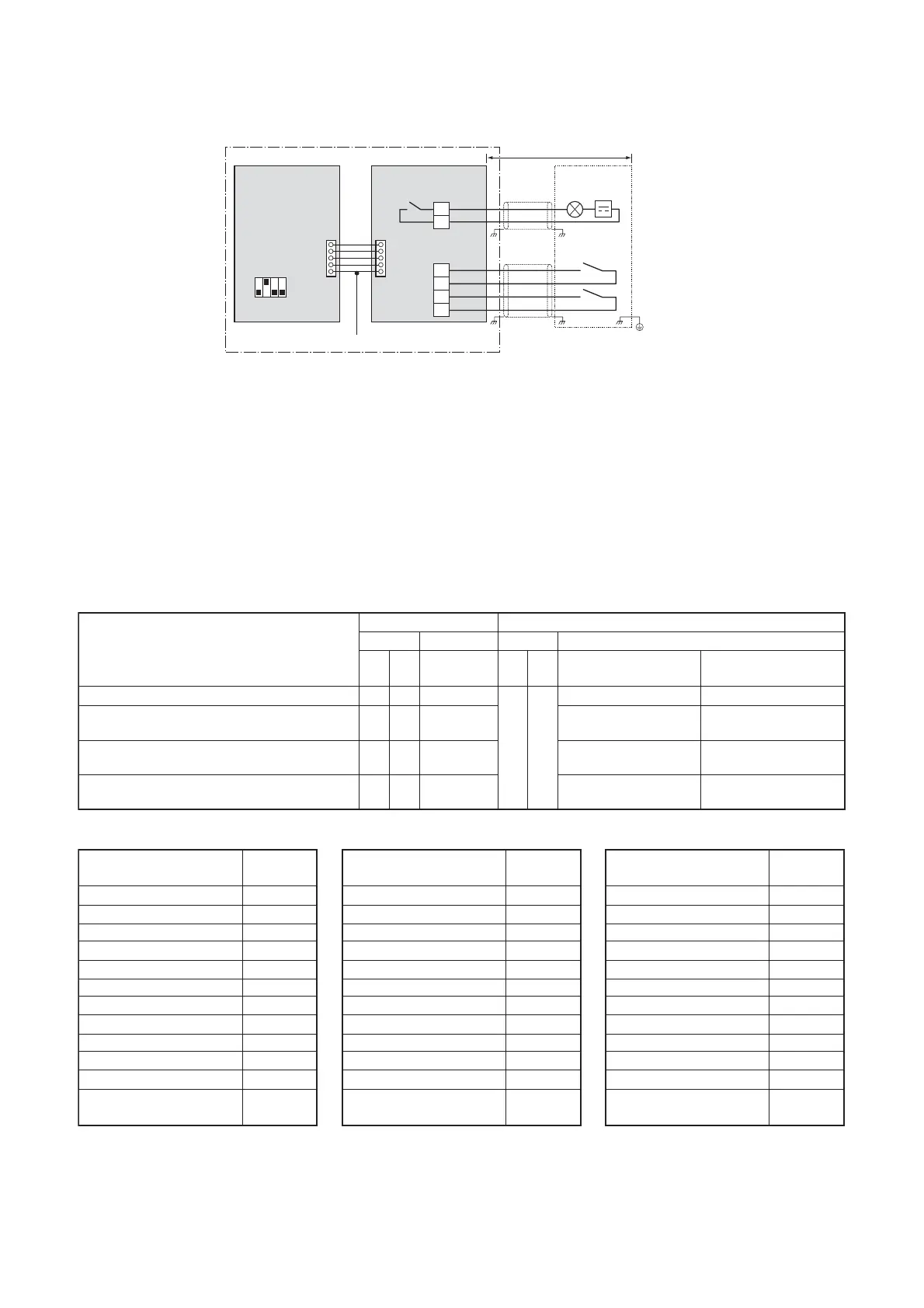
Optional P.C.board Outdoor unit interface P.C.board
*The upper limit X%, Y%, Z% can be regulated with the outdoor DN Code (O.DN) [00E] [00F] [010].
Demand: power peak-cut control
[4-stage switching] <SW105 Bit1 ON, Bit2 ON>
Display relay SW105
Outdoor DN Code [
∗∗∗
]
SW1
Input
Control item
SW2 (L1) Bit1 Bit2
Factory default [00E] = 15,
[00F] = 8, [010] = 4
[00E] = X, [00F] = Y,
[010] = Z
Input demand OFF signal to release the demand
Outdoor unit DN Code (O.DN)
[00E]
X
0
1
2
3
4
5
6
7
8
9
10
100%
95%
90%
85%
80%
75%
70%
65%
60%
55%
50%
15 (factory default)
0%
(forced stop)
OFF OFF OFF
OFF ON
100% (normal operation) 100% (normal operation)
Input demand ON signal to control the demand ON OFF ON
Approx. 80%
(upper limit regulated)
Approx. Z% (50% to 100%)
(upper limit regulated)
Input demand ON signal to control the demand OFF ON ON
Approx. 60%
(upper limit regulated)
Approx. Y% (50% to 100%)
(upper limit regulated)
Input demand ON signal to control the demand ON ON ON 0% (forced stop)
Approx. X% (50% to 100%)
(upper limit regulated)
Outdoor unit DN Code (O.DN)
[00F]
Y
0
1
2
3
4
5
6
7
8 (factory default)
9
10
100%
95%
90%
85%
80%
75%
70%
65%
60%
55%
50%
15
0%
(forced stop)
Outdoor unit DN Code (O.DN)
[010]
Z
0
1
2
3
4 (factory default)
5
6
7
8
9
10
100%
95%
90%
85%
80%
75%
70%
65%
60%
55%
50%
15
0%
(forced stop)
PJ17
TB1
[ON]
[OFF]
TB2
COM
ON
COM
OFF
CN513
SW105
Bit1 OFF, Bit2 ON
L1
SW1
ON
OFF
1234
SW2
Connection cable
Locally procured
[OPERATION]
L1: Display lamp ensuring power peak cut control
Optional PCB
Header outdoor unit
Shield wire
Shield wire
Outdoor unit
interface PCB
Display
relay
Power
supply
For SW1 and SW2, be sure to provide
no-voltage contacts for each terminal.
The optional P.C. board should be connected to the header outdoor unit (U1).
6-6-3-2. Power peak-cut Control (Extended)
Operation
The demand request signal from the outside restricts the maximum capability (or maximum electric power)
of an outdoor unit.
L1: Power peak-cut control indication lamp
SW1: Power peak-cut control ON switch*1
SW2: Power peak-cut control OFF switch*1
*1 The inputs of SW1 and SW2 can be either pulse (100 msec or longer) or step signals.
* Be sure to provide a contact for each terminal.
Extended power peak-cut control settings
 Loading...