(5) Display of Indoor Unit Information (Displayed on Header Unit Only)
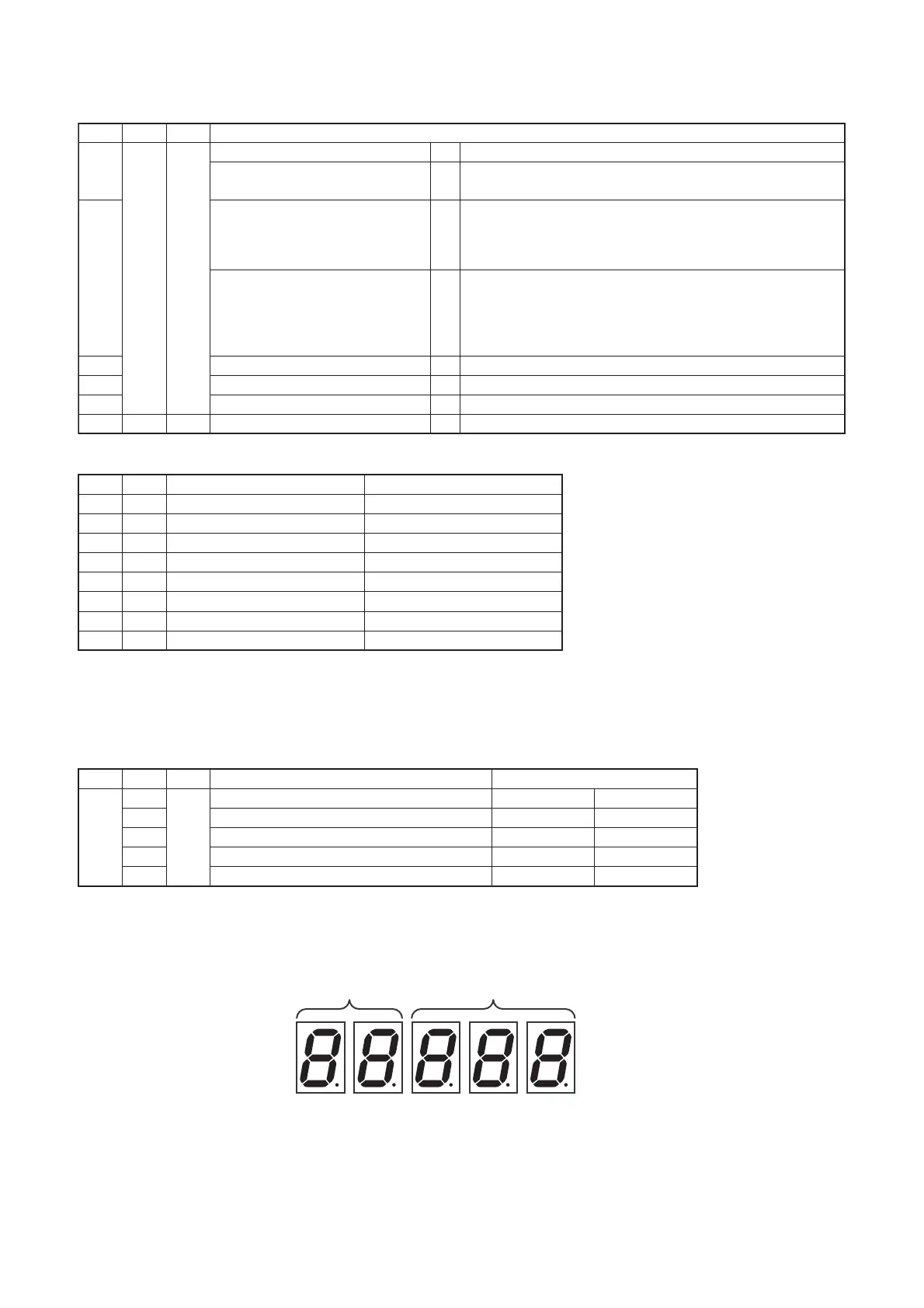
Note: Indoor address No. is selected by setting SW02 and SW03 and displayed on 7-segment display, section A.
(6) Display of Outdoor EEPROM Writing Check Code (Displayed on Header Unit Only)
* The latest check code written in the EEPROM of each outdoor unit is displayed.
(This function is used to check the trouble code after the resetting of the power supply.)
To display the check code, push SW04 and hold for at least 5 seconds after setting SW01 to 03 as shown in
the table below.
• 7-Segment Display
Set SW01/SW02/SW03 to [1/1/16] and push SW04 and hold for at least 5 seconds. The latest check code of
the header unit (U1) will be displayed.
If the setting of SW02 is changed, the latest check code of a follow unit (U2-U5) will be displayed.
4
Indoor check code B No check code : [- - -]
6 Indoor PMV opening data B Displayed in decimal format
7 Indoor temperature sensor data1 B
Switch temperature display of TA, TCJ, TC1 and TC2 with SW06
8 Indoor temperature sensor data2 B Switch temperature display of TF, TA2 and TA3 with SW06
5
Indoor HP capacity B ... 0.3, ...0.4, ...0.5, ...0.6
... 0.8, ...1.0, ...1.2, ...1.7, ...2.0
... 2.5, ...3.0, ...3.2, ...4.0, ...5.0
... 6.0, ...8.0, ...10.0, ...16.0, ...20.0
1~16 1~8 Indoor request command
(S code, operation mode)
B [#.... *]
# represents mode :
COOL : [C. ... *], HEAT : [H … F]
FAN : [F. ... *], OFF : [S … *]
* represents S code : [#. … 0] to [#. … F]
9 1 1 Outdoor DN code setting
Outdoor DN code setting
Indoor BUS communication signal
receiving status
B Upon receiving signal : [... ... 1], Other times : [...... ...]
SW01 SW02 SW03 Display detail
SW02 SW03 Indoor address 7-segment display section A
1
2
3
4
5
6
7
8
1 ~ 16
1 ~ 16
1 ~ 16
1 ~ 16
1 ~ 16
1 ~ 16
1 ~ 16
1 ~ 16
SW02 setting number
SW02 setting number +16
SW02 setting number +32
SW02 setting number +48
SW02 setting number +64
SW02 setting number +80
SW02 setting number +96
SW02 setting number +112
[01] ~ [16]
[17] ~ [32]
[33] ~ [48]
[49] ~ [64]
[65] ~ [80]
[81] ~ [96]
[97] ~ [112]
[113] ~ [128]
SW01 SW02 SW03 Indoor address 7-segment display section A
1 Latest check code of header unit (U1) E. 1.
2 Latest check code of follower unit No. 1 (U2) E. 2.
3161 Latest check code of follower unit No. 2 (U3) E. 3.
∗∗∗
∗∗∗
∗∗∗
4
Latest check code of follower unit No. 3 (U4) E. 4. ∗∗∗
5
Latest check code of follower unit No. 4 (U5) E. 5. ∗∗∗
Section A
Section B
 Loading...