TC Series (TCmini/TC200) Driver
GP-Pro EX Device/PLC Connection Manual
75
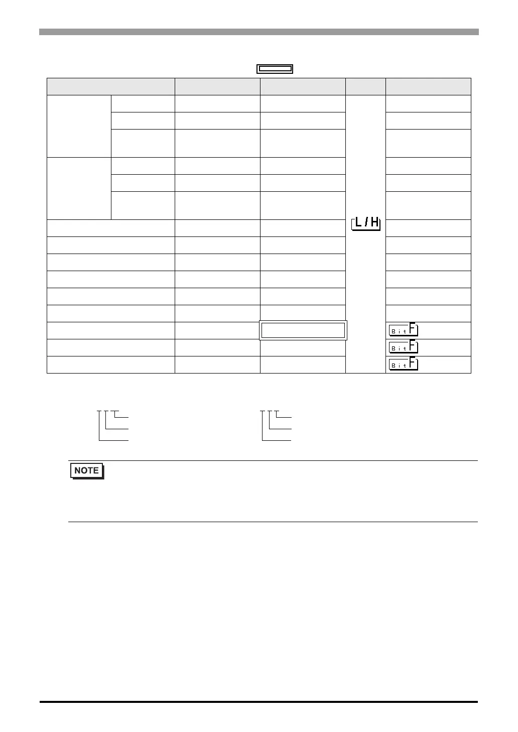
TC8-00/TC5-02
This address can be specified as system data area.
Device Bit Address Word Address 32 bits Notes
External Input
Relay
Photo coupler X000 - X00F X00W - X00W
*1
*1 Device format is as follows:
Please refer to the manual of external device for more detail.
DIP Switch X010 - X017 X01W - X01W
*1
Extended Panel
Switch
X100 - X11F X10W - X11W
*1
External Output
Relay
Transistor Y020 - Y02B Y02W - Y02W
*1
Relay Contact Y02C - Y02F Y02W - Y02W
*1
Extended Panel
LED
Y140 - Y14F Y14W - Y14W
*1
Internal Relay R000 - R77F R00W - R77W
*1
Edge Relay E000 - E17F E00W - E17W
*1
Latch Relay L000 - L07F L00W - L07W
*1
Timer Relay T000 - T27F T00W - T27W
*1
Counter Relay C000 - C27F C00W - C27W
*1
Special AUX Relay A000 - A16F A00W - A16W
*1
Data Register ------ D000 - D77F
*1
T/C Register 1 ------ P000 - P27F
*1
T/C Register 2 ------ V000 - V27F
*1
• Please refer to the GP-Pro EX Reference Manual for system data area.
Cf. GP-Pro EX Reference Manual "LS Area (Direct Access Method Area)"
• Please refer to the precautions on manual notation for icons in the table.
)"Manual Symbols and Terminology"
E.g.
X 0
0 W
Register Word Specified
Position (0 to 7)
Rack No. (0 to F)
D F
7 F
Port No. (0 to F)
Position (0 to 7)
Rack No. (0 to F)
 Loading...


