TC Series (TCmini/TC200) Driver
GP-Pro EX Device/PLC Connection Manual
77
TC3-01
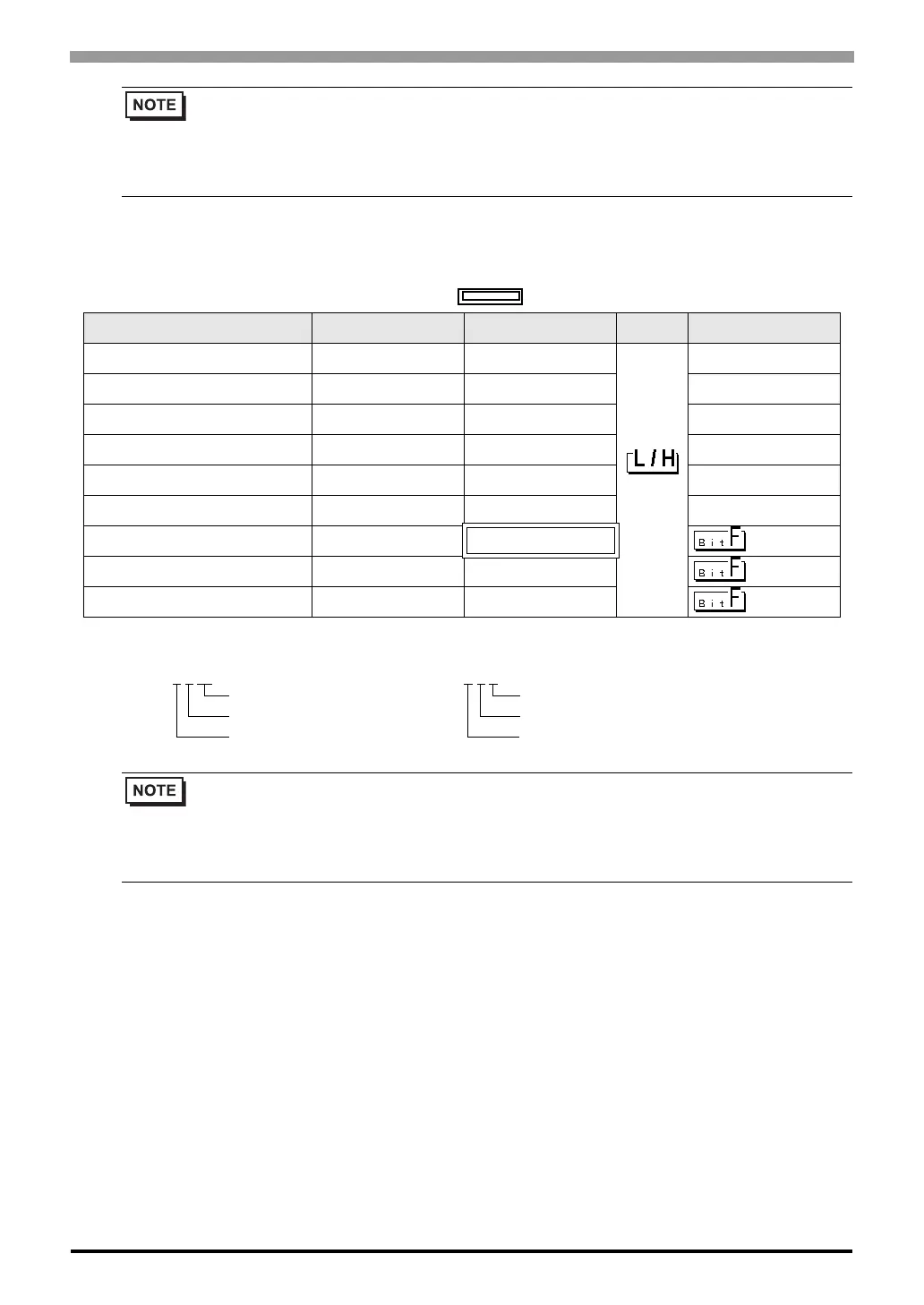
This address can be specified as system data area.
• Please refer to the GP-Pro EX Reference Manual for system data area.
Cf. GP-Pro EX Reference Manual "LS Area (Direct Access Method Area)"
• Please refer to the precautions on manual notation for icons in the table.
)"Manual Symbols and Terminology"
Device Bit Address Word Address 32 bits Notes
External Input Relay X000 - X00B X00W - X00W
*1
*1 Device format is as follows:
Please refer to the manual of external device for more detail.
External Output Relay Y000 - Y00B Y00W - Y00W
*1
Internal Relay R000 - R17F R00W - R17W
*1
Timer Relay T000 - T05F T00W - T05W
*1
Counter Relay C000 - C05F C00W - C05W
*1
Latch Relay L000 - L01F L00W - L01W
*1
Data Register ------ D000 - D22F
*1
T/C Register 1 ------ P000 - P05F
*1
T/C Register 2 ------ V000 - V05F
*1
• Please refer to the GP-Pro EX Reference Manual for system data area.
Cf. GP-Pro EX Reference Manual "LS Area (Direct Access Method Area)"
• Please refer to the precautions on manual notation for icons in the table.
)"Manual Symbols and Terminology"
E.g.
X 0
0 W
Register Word Specified
Position (0 to 7)
Rack No. (0 to F)
D F
7 F
Port No. (0 to F)
Position (0 to 7)
Rack No. (0 to F)
 Loading...


