E6581288①
− 29 −
6.3. How to check the error using the LEDs
The following example explains the causes of fault which may be judged from the LED
status of the CC-Link unit (CCL001Z) of the inverter.
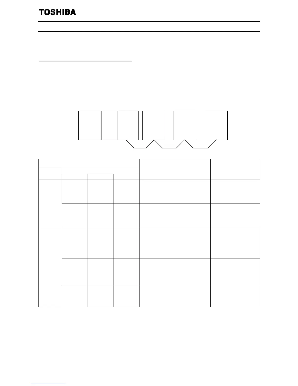
(1) When two or more inverters are connected
The following example explains the causes and corrective actions for fault which may be
judged from the LED status of the CC-Link units (CCL001Z) of the inverters under the
condition that the SW, M/S and PRM LEDs of the master unit are off (the master unit
setting is proper) in the system configuration shown below:
Power CPU Master
supply unit
Station 1
Inverter
Station 2
Inverter
Station 3
Inverter
LED Status
CCL001Z
Master
unit
Station 1 Station 2 Station 3
Cause Corrective Action
L.RUN ●
SD ●
RD ●
L.ERR ○
L.RUN ●
SD ●
RD ●
L.ERR ○
L.RUN ●
SD ●
RD ●
L.ERR ○
Normal
−
TIME○
LINE○
or
TIME●
LINE○
L.RUN ○
SD ○
RD ○
L.ERR ○
L.RUN ●
SD ●
RD ●
L.ERR ○
L.RUN ●
SD ●
RD ●
L.ERR ○
Poor contact of the CCL001Z
with the inverter.
Plug the CCL001Z
securely.
Check the connector.
L.RUN ●
SD ●
RD ●
L.ERR ○
L.RUN ○
SD *
RD *
L.ERR ○
L.RUN ○
SD *
RD *
L.ERR ○
Since the L.RUN LEDs of the
CCL001Z on station 2 and later
are off, the communication cable
between the unit 1 and 2 is open
or disconnected from the
terminal block.
Referring to the LED
"on" condition, search
for an open point and
repair.
L.RUN ○
SD *
RD *
L.ERR ○
L.RUN ○
SD *
RD *
L.ERR ○
L.RUN ○
SD *
RD *
L.ERR ○
The communication cable is
shorted.
Among the three wires
of the communication
cable, search for
shorted wire and
repair.
TIME●
LINE●
or
TIME○
LINE●
L.RUN ○
SD *
RD *
L.ERR *
L.RUN ○
SD *
RD *
L.ERR *
L.RUN ○
SD *
RD *
L.ERR *
The communication cable is
wired improperly.
Check the wiring on
the inverter terminal
block and correct the
improper wiring point.
●: On, ○: OFF, ◎: Flicker, *: Any of on, flicker or off.
 Loading...