EasyManua.ls Logo

Toshiba Vm Series User Manual

Toshiba Vm Series
99 pages
To Next Page IconTo Next Page
To Previous Page IconTo Previous Page
Page #75 background imageLoading...
Page #75 background image
Unified Controller Vm series TC-net 100(TNB) Module Manual
61
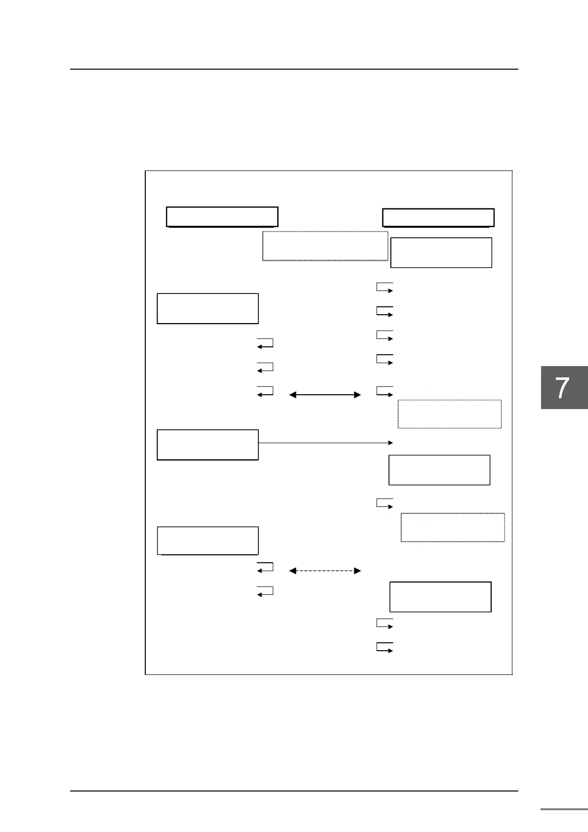
7.1.3 Timing of generation of information by socket
The timing of setting and clearing information by socket when opened as
TCP/IP and closed after data transmission is shown below.
単位情
TCP
(コ:35Hind
アクティクライアント)
(注:ーバ側は先にオー要求を行い、
イアントからの接続要求に備す)
パッ(サ
TCP
(コ:35Hind
socket (*1)
<TCP>=1
bind
listen
socket
<TCP>=1
bind
connect
<AOP>=1,<CON>=1
accept
(新しットを成)
<TCP>=1,<POP>=1,<CON>=1
(注:*1 生成したソケッ
命令語にてcoseれます
TCP 要求
(コ:37H
(データ着信)
<RCV>=1
TCP 受信要
(コ:38H
recv
<RCV>=0
(注:RCV は着信データが有る場
合に ON、合に OFF)
TCP ロー
(コ:39H
shutdown
close
=
(リモートロー出)
<RCL>=1,<CON>=0
TCP ロー
(コ:39H
shutdown
close
=
select
(Note) When running the controller and then halting it, close is requested by the controller basic
software for the socket used by the controller.
Figure 7-3 Information by socket and clear timing (1)
(New socket is generated)
Information by socket
Active (client)
Passive (server)
Note: The server side makes an
open request first to prepare for the
connection request from the client.
TCP open request
(Command: 35H, kind=2)
TCP open request
(Command: 35H, kind=1)
Note: The socket generated at
*1 is closed by the instruction
word.
TCP close request
(Command: 39H)
TCP reception request
(Command: 38H)
TCP transmission
request
(Command: 37H)
TCP close request
(Command: 39H)
(
Remote close detected
)
All bits=0
Note: RCV is ON when there
is received data and OFF
otherwise.
(Data reception)

Other manuals for Toshiba Vm Series

Questions and Answers:

Toshiba Vm Series Specifications

General IconGeneral
BrandToshiba
ModelVm Series
CategoryController
LanguageEnglish

Summary

Safety Precautions

Description of Signs

Details signs like DANGER, WARNING, CAUTION and their meanings.

Description of Symbols

Explains symbols like Prohibited and Mandatory, and their meanings.

Installation Safety Precautions

Environment, Grounding, and Ventilation Safety

Covers safe installation environments, grounding, ventilation, and cable handling.

Maintenance and Inspection Safety

Module Handling and Static Electricity Safety

Emphasizes power safety, static discharge, and safe handling of modules during maintenance.

Replacement and Daily Use Safety

Life Limited Parts and Daily Operation Safety

Covers safety during replacement, daily operation, modification, and condition monitoring.

Transport, Storage, and Disposal Safety

Handling, Storage, and Disposal Precautions

Safety measures for handling internal components, cables, transportation, storage, and disposal.

Application Restrictions and Disclaimers

Application Use Restrictions

Specifies restrictions on using the product in systems affecting human life or public functions.

Introduction to the TNB Module

Manual Overview and Related Documents

Introduces the manual's content and lists related documents for comprehensive understanding.

Document Conventions and Structure

Notational Conventions Explained

Defines symbols like Important, Note, and Remark for better document comprehension.

Chapter 1: Introducing the TNB

TNB Module Functions and Characteristics

Describes the TNB module's role, network type, and its key characteristics like openness and reliability.

TNB Module Parts Identification

Details the physical components and their functions on the TNB module.

TNB Module Parts Identification Details

TNB21/TNB22 Part Names and Labels

Identifies and labels the physical components of the TNB21 and TNB22 modules.

TNB Module Part Functions

State Display LED Functionality

Explains the meaning of each state display LED (RUN, ERR, SCAN, LNK, ACT) and their normal display states.

TNB Module Settings and Connections

Station Address and Operation Mode Switches

Describes the function of STN-H/L and MODE switches for setting address and operation mode.

TC-net 100 Connector Details

Details the TN-A and TN-B connectors for TC-net 100 communication using optical fiber.

Chapter 2: Installation and Wiring

Preparation for Installation and Wiring

Installation Safety and Prohibitions

Safety warnings before installation, prohibited actions, and required tools/environment.

Installing the TNB Module

Module Insertion and Securing Procedure

Details the procedure for inserting the TNB module into the basic unit and securing it.

Connecting the TC-net 100 Cable

Optical Fiber Cable Handling and Safety

Steps for connecting the optical fiber cable, including dust cover removal and cable securing, with safety warnings.

Replacing the TNB Module

TNB Module Replacement Procedure

Step-by-step guide for replacing the TNB module, including powering off and handling precautions.

Chapter 3: Setting

TNB Module Switch Settings

Station Address Configuration

Explains how to set the station address using hexadecimal rotary switches (STN-H, STN-L).

TNB Module Operation Modes

Operation Mode and IP Address Settings

Details the DIP switch settings for operation mode and IP address types.

Network Parameter Configuration

Network ID and Subnet Mask Settings

Describes how to set Network ID and Subnet Mask for different IP address types.

TC-net Addressing and Multicast

Station Address Assignment and Multicast

Guidelines for station address assignment and an overview of supported multicast addresses.

Configuration Using Engineering Tool

Ethernet System and IP Settings

Illustrates Ethernet configuration and guidance for IP address and switch settings.

TNB Network Parameter Setup

Registering Stations and Units in Tool

Steps to register the TNB module as a station and add units using the engineering tool.

Configuring CPU Functions

Adding CPU Features via Engineering Tool

Instructions on how to add CPU features in the engineering tool's product tree.

Adding TNB Extended Modules

Registering TNB Expansion Cards

Details on selecting and registering TNB21/TNB22 as expansion cards with relevant details.

TNB Module Parameter Configuration

Module Parameter Registration and IP Settings

Shows the parameter screen and guide to registering IP address type, IP address, and subnet mask.

Applying TNB Configuration

Downloading and Restarting Configuration

Instructions for downloading configuration data and restarting the controller for changes to take effect.

Network Setup in Engineering Tool

Setting Network Topology and Adding LAN

Steps to set the network from the product tree and add a TC-net 100LAN network.

Establishing TC-net 100LAN Connection

Adding Modules to TC-net 100LAN

Procedure to add the TNB module to the TC-net 100LAN network using the Add Module dialog.

Verifying TNB Configuration

Obtaining and Confirming TNB Information

Connects via Ethernet to retrieve and verify TNB module information after setup.

Configuring Scan Talker Blocks

Registering Scan Talker Blocks in Tool

Steps to set scan talker blocks from the product tree and register each block with its parameters.

Scan Talker Block Settings Verification

Verifying Scan Talker Block Parameters

Checks the transmission speed and slot information displayed in the talker block parameter screen.

Finalizing Scan Talker Block Configuration

Downloading and Checking Talker Block Data

Downloads scan talker block data and confirms its registration after download.

Configuring State Change Notification

State Change Notification Parameters

Details parameters for state change detection, including scan data block/word, bit mask, timing, and controller slot.

Applying State Change Notification Settings

Downloading and Verifying Notification Data

Downloads state change notification data and verifies its successful application.

Chapter 5: Troubleshooting

Troubleshooting with LEDs

LED Fault Diagnosis Table

Provides a table to diagnose faults by observing the status of the TNB module's LEDs.

Network Information and Diagnostics

Scan Healthy Map Reference

Explains how to display and interpret the scan healthy map to check the status of scan data blocks.

LAN Management Information

Accessing LAN Management Data

Details how to access LAN management information for nodes connected to TC-net 100LAN.

Detailed LAN Management Information

Viewing Detailed Node Counters

Explains how to view detailed counters by clicking 'Detailed' in the LAN management information screen.

Receiving Line Control

Switching TC-net 100 Receiving Lines

Describes how to switch the receiving line (Auto, Force A, Force B) for TC-net 100.

In-Ring Map Visualization

Displaying TC-net 100 Station Status

Explains the in-ring map which shows the state of stations on the TC-net 100 network.

TNB Module Option Functions

Self Healthy Mode Configuration

Details how to set the TNB to self healthy mode for maintaining scan healthy status during transmission path errors.

RAS Information Block Setup

RAS Information for Scan Transmission

Explains how to register RAS information generated by TNB into scan blocks for transmission.

Chapter 4: Operation

TNB Module Operation Procedures

Pre-Operation Checks and Startup

Lists pre-operation checks and describes startup and shutdown procedures for the TNB module.

Chapter 5: Troubleshooting

Troubleshooting with LEDs

LED Fault Diagnosis Table

Provides a table to diagnose faults by observing the status of the TNB module's LEDs.

Chapter 6: Maintenance and Inspection

Maintenance and Inspection Safety Precautions

Safe Handling and Error Procedures

Safety measures for handling product interior, static discharge, and cable stress during maintenance.

Product Inspection Procedures

Daily Inspection Checklist

Items to check during daily inspection, including LEDs, connectors, ventilation holes, and indoor environment.

Life Limited Parts Replacement

Optical Module Replacement Cycle

Recommends regular replacement of life-limited parts, specifically the optical module, based on usage time or power loss.

Chapter 7: Application Interface

Socket Information Configuration

Application Information Structure on Station Bus

Explains the configuration of application information on the station bus via sockets, including address mapping.

Socket Information Details

Socket State Information Bits Explained

Details the conditions that make each bit '1' or '0' in the socket state information.

Accessing Socket Information

Station Bus Address Mapping by Slot

Shows how base addresses and starting word addresses for socket information vary based on TNB installation slots.

Socket Information Timing

TCP/IP Socket Communication Timing

Illustrates the timing of setting and clearing socket information during TCP/IP communication.

Transmission Path Diagnosis

Scan Data Healthy Map Configuration

Explains how the scan data healthy map is managed and its bit meanings for healthy/unhealthy states.

Scan Data Unhealthy Map

Scan Data Unhealthy Map Configuration

Describes the scan data unhealthy map, its bit meanings, and the condition for detecting unhealthy states.

Scan Data Talker Map

Scan Data Talker Map Configuration

Explains the scan data talker map, displaying sending station addresses and overlapping source addresses for scan blocks.

RAS Information Configuration

RAS Information for TN8 and TNB Nodes

Details the configuration of RAS information provided by TN8 and TNB nodes, including module type and healthy counters.

In-Ring Map Configuration

Displaying TC-net 100 Station Status

Explains the in-ring map which shows the state of stations on the TC-net 100 network.

Usage Constraints

Port Number Restrictions

Specifies reserved port numbers and the range of usable port numbers for the TNB module.

Appendix A: Specifications

General Specifications

Lists general specifications for TNB21 and TNB22 modules, including operating temp, humidity, voltage, etc.

TC-net 100 Transmission Specifications

Provides detailed transmission specifications for the TC-net 100 network.

Function Specifications

Outlines the transmission methods and monitoring functions (RAS) of the TNB module.

Appendix B: Outside Dimensions

TNB21/TNB22 Module Dimensions

Shows the physical dimensions of the TNB21 and TNB22 modules, including width, depth, and height.

Appendix C: Related Products

Recommended Optical Fiber Cable

Lists related products, specifically the optical fiber cable with MT-RJ connectors for the TNB module.

Appendix D: Decimal-Hexadecimal Conversion

Decimal to Hexadecimal Conversion Table

Provides a table for converting decimal numbers to their hexadecimal equivalents.

Related product manuals