CGWF-SVX01A-EN 21
Installation Mechanical
Alternate Moving Methods
If it is not possible to rig from the previous method shown inFigure 4 and Figure 5,
the unit my also be moved by jacking each end high enough to move an equipment
dolly under each end of the unit frame. Once securely mounted on the dollies, the
unit may be rolled into position. Jacks should be positioned to lift under the lifting
angles installed on the unit by the contractor.
Access Restrictions
All CGWF/ CCAF units will pass through a standard 36-inch doorway. Typical
dimensions are shown in Figure 7 - Figure 11.
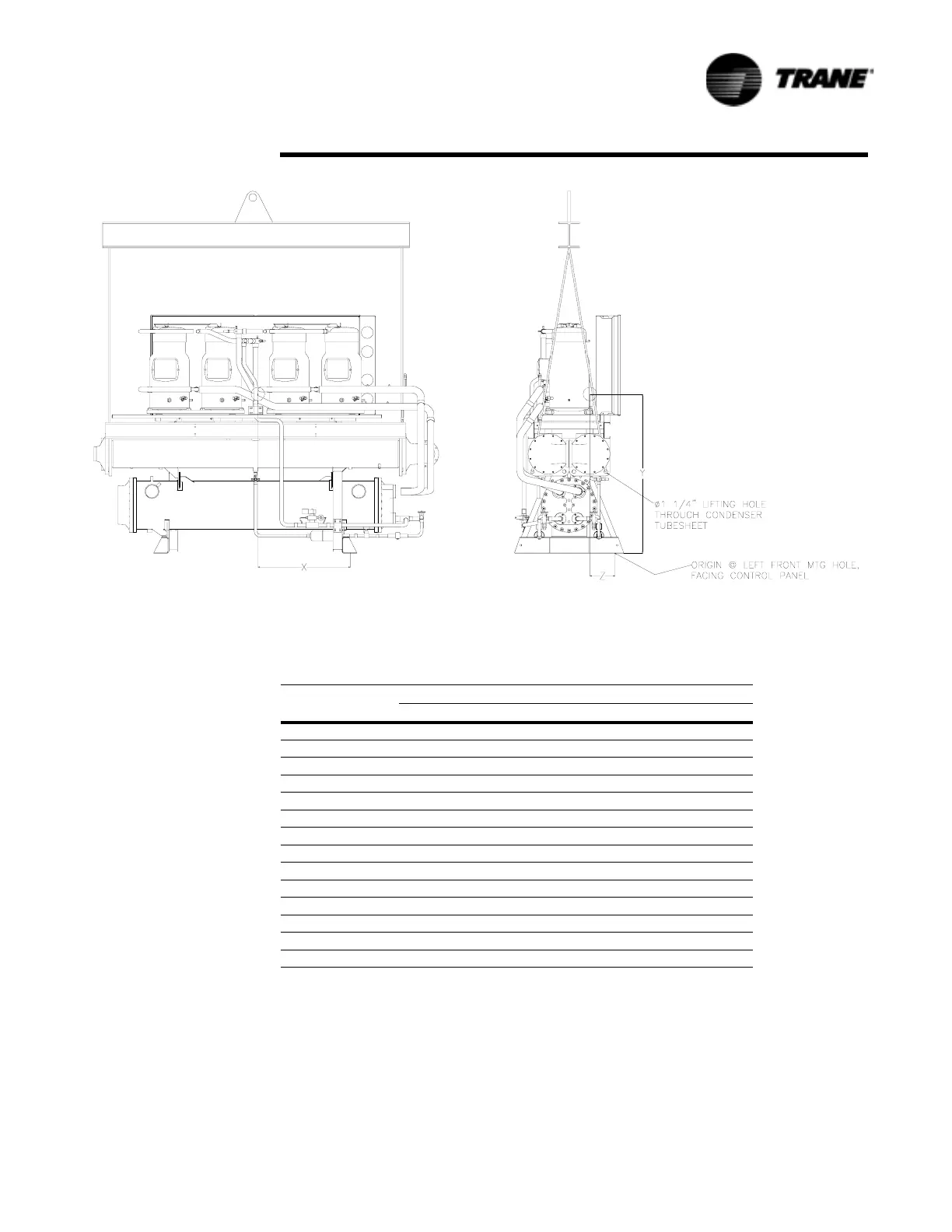
Figure 5 Typical Rigging Setup For CGWF 60 Ton Units.
1. Use clevis pins for attachment of chains to lifting
holes, lifting chains (cables) may be adjusted for
level lifting.
2. Do not Forklift Unit.
3. All units are heavier on the control panel side. Use
Table 5 to adjust rigging accordingly.
4. Minimum beam length 6ft.
Table 5 Center of Gravity Dimensions
Unit Size Location of Center of Gravity (in)
XYZ
CGWF
20 18 24 9
25 18 25 9
30 18 26 9
40 23 26 8
50 23 27 9
60 28 31 13
CCAF
20 28 31 8
25 28 30 8
30 28 28 8
40 33 29 8
50 33 27 8
60 33 26 8
 Loading...


