32 CGWF-SVX01A-EN
Installation Mechanical
Evaporator Water Piping
Evaporator Water Connections.
Internal NPTF water inlet and outlet connections are used on all 20 through 50 ton
CGWF and 20-60 ton CCAF units. 60 ton CGWF use grooved pipe connectors for
water inlet and outlet. Evaporator water inlet and outlet types, sizes and locations are
shown in Figure 14.
Evaporator Piping Components
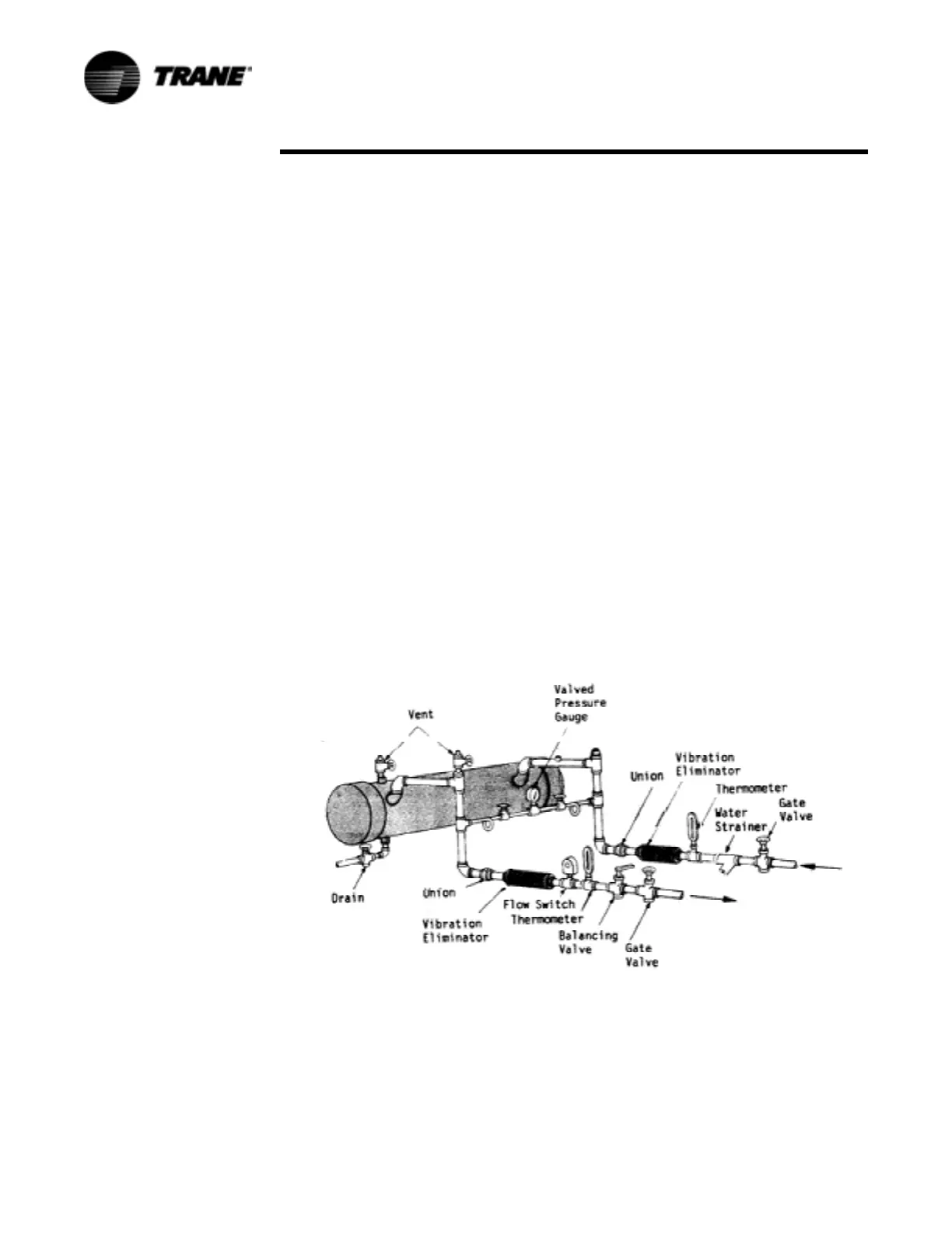
Figure 14 illustrates typical recommended evaporator piping components. Piping
components and layout vary, depending on water source and connection locations. A
vent is located on top of the evaporator at the water outlet end. Provide additional
vents at high points in the piping to bleed air from the chilled water system. Install
pressure gauge(s) to monitor entering and leaving chilled water pressure.
CAUTION
Excessive Water Pressure!
To prevent evaporator damage, do not exceed 300 psi for 20-60 ton CCAF
and 20-50 ton CGWF, and 215 psi for 60 ton CGWF evaporator water
pressure.
Provide shutoff valves in the line(s) to the gauge(s) to isolate the gauges when not in
use. Use pipe unions to simplify disassembly for system service. Use vibration
eliminators to prevent transmitting vibrations through the water lines.
Install thermometers in the lines to monitor evaporator entering and leaving water
temperatures. Install a balancing cock in the leaving water line. It will be used to
establish a balanced water flow. Both the entering and leaving water lines should
have shutoff valves installed to isolate the evaporator for service.
Flow Sensing Devices
Chilled water flow switches are optional, but there must be a chilled water flow
interlock provided to the MP to indicate that the evaporator pump is running. To
provide additional chiller protection, install and wire the flow switch in series with the
chilled water pump interlock for the chilled water circuits (refer to “Chilled Water Flow
Interlock”). Specific connection and schematic wiring diagrams shipped with the unit.
Figure 14 Recommended Piping
 Loading...


