22 CGWF-SVX01A-EN
Installation Mechanical
Recommended Clearances
Provide recommended access clearance for service and maintenance operations.
Refer to recommendations provided in Figure 7 - Figure 11. Local codes may take
precedence over recommendations.
Unit Isolation
There are two mounting methods that will minimize sound and vibration. They are the
direct-mount method and the isolator-mount method.
Direct Mounting
The unit can be direct-mounted on an isolated concrete pad or on an isolated concrete
footing at each end. Refer to Table 3 and Table 4 for unit operating weights. A
mounting hole is provided in the base of the unit frame at each mounting location.
Provide a means of securely anchoring the unit to the mounting surface. Level the
unit carefully. Refer to “Leveling the Unit”.
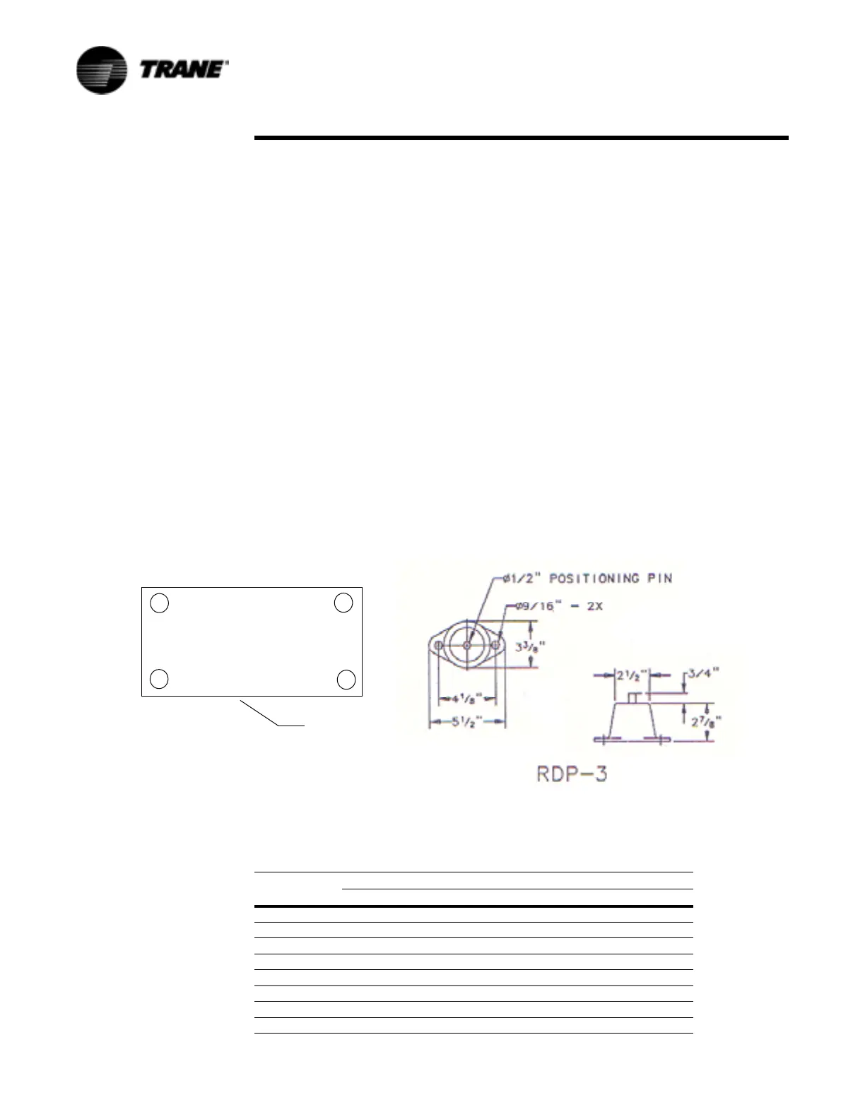
Neoprene Isolator Mounting
Install the optional neoprene mounting isolators at each mounting location. Refer to
Table 6 for isolator selection, placement and loading information. Isolators are
identified by color and by the isolator part number.
Bolt the isolator to the mounting surface. Do not fully tighten the mounting bolts.
Mount the unit on the isolators and install a 1/2-inch (13 mm) nut on each isolator
positioning pin. Maximum isolator deflection should be 1/4-inch. Level the unit
carefully. Refer to “Unit Leveling”. Now fully tighten isolator mounting bolts.
Neoprene Isolator Data
Figure 6 Isolators and Locations
3
1
4
2
Control
Panel End
CGWF/CCAF
Table 6 RDP 3 Neoprene Isolator Selection
Unit Size
Location
1234
CGWF
20 Green Green Green Green
25 Green Green Green Green
30 Green Green Green Green
40 Gray Gray Gray Gray
50 Gray Gray Gray Gray
60 Gray Gray Gray Gray
CCAF
 Loading...


