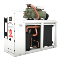
RLC-SVX023A
12
4 UNT-PRC002-GB
Technical Data
FWD 08 12 20 30 45
Power supply (V/Ph/Hz) 230/1/50
Capacities
Cooling capacity on water (1) (kW) 5,2 8,3 15 18,8 30,1
Heating capacity on water (2) (kW) 6,3 11,9 18,9 20,9 38,2
Fan motor (type) 2 x direct drive centrifugal
Fan power input (3) (kW) 0,23 0,46 0,65 1,04 1,51
Current amps (3) (A) 1,1 2,2 3,1 4,7 5,5
Start-up amps (A) 3,2 5,5 9,3 14,1 16,5
Air flow
minimum (m
3
/h) 490 980 1400 1800 2700
nominal (m
3
/h) 820 1650 2300 3000 4500
maximum (m
3
/h) 980 1970 2600 3600 5400
Main coil
Water entering/leaving connections (type) ISO R7 rotating female
(Dia) 3/4" 3/4" 1 1/2" 1 1/2" 1 1/2"
Electric heater (accessory for blower only)
Electric power supply (V/Ph/Hz) 230/1/50 230/1/50 or 400/3/50 400/3/50 400/3/50 400/3/50
Heating capacity (kW) 2/4 8 10 12 12
Hot water coil (accessory for blower only)
Heating capacity (4) (kW) 6,3 12 17,4 22,4 34,5
G2 filter (filter box accessory)
Quantity 2 2 2 2 2
Dimensions ( LxWxth) (mm) 386x221x8 486x271x8 586x321x8 586*421*8 586*621*8
G4 filter (filter box accessory)
Quantity - 2 2 2 2
Dimensions ( LxWxth) (mm) - 486x264x48 586x314x48 586*414*48 586*614*48
Condensate pump (accessory) (type) Centrifugal
Water flow - lift height (l/h - mm) 24 - 500
Not available for FWD30 and FWD45
Sound level (L/M/H speed)
Sound pressure level (5) (dB(A)) 36/40/43 38/41/44 46/50/53 47/52/57 47/52/58
Sound power level (5) (dB(A)) 46/50/53 48/51/54 56/60/63 57/62/67 57/62/68
Unit dimensions
Width x Depth (mm) 890 x 600 1090 x 710 1290 x 820 1290 x 970 1290 x 1090
Height (mm) 250 300 350 450 650
Shipped unit dimensions
Width x Depth (mm) 933 x 644 1133 x 754 1333 x 864 1333 x 1008 1333*1133
Height (mm) 260 310 360 460 660
Weight (kg) 32 46 61 76 118
Colour galvanised steel
Recommended fuse size
Unit alone (aM/gI) (A) 8/16 8/16 8/16 8/25 8/25
Unit with electric heater (gI) (A) 16 (2kW),25 (4kW) 40 (230V),3*16 (400V) 3*20 3*25 3*25
(1) Conditions: Water entering/leaving temperature: 7/12 °C, Air inlet temperature 27/19°C DB/WB - Nominal air flow
(2) Conditions: Water entering/leaving temperature: 50/45 °C, Air inlet temperature 20°C DB - Nominal air flow
(3) At high speed with nominal air flow.
(4) Water entering/leaving temperature 90/70 °C, air inlet temperature 20 °C DB, Nominal air flow.
(5) A rectangular glass wool duct 1m50 long is placed on the blower.The measurement is taken in the room containing the blower unit.
Heat exchanger operating limits:
FWD:
*water temperature: max 100° C
*absolute service pressure: min 1 bar/max 11 bars
Accessories - Hot water coil:
*water temperature: min. +2° C/max. 100° C
*absolute service pressure: min 1 bar/max 11 bars
Installation - Mechanical
Unit Leveling
NOTE: The electrical panel side of the unit is designated
as the “front” of the unit.
1. Check unit level end-to-end by placing a level on the
chiller structure (compressor frame for example).
2. Adjust to within 5 mm of level front-to-back.
Water Piping
Piping Connections
To prevent equipment damage, bypass the unit if using
an acidic flushing agent.
Make water piping connections to the evaporator
and condenser. Isolate and support piping to prevent
stress on the unit. Construct piping according to local
and national codes. Insulate and flush piping before
connecting to unit.
The chilled water connections to the evaporator are to be
grooved-pipe type connections. Do not attempt to weld
these connections. Refer to submittal for dimension of
tube stub for grooved connection. Refer to submittal for
dimension of tube stub for grooved connection.
To prevent damage to chilled water components, do not
allow evaporator pressure (maximum working pressure)
to exceed 10 bar.
Reversing Water Connections is prohibited
It is critical to keep the factory layout for water
connections. Therefore reversing water connections may
lead to functional disorder.
NOTE: Dimensions of tube stub for grooved connection
are included in submittal drawings.
Vents and Drains
Install pipe plugs in evaporator and condenser water
connections drain and vent connections before filling
the water systems. To drain water, remove vent and drain
plugs, install a NPT connector in the drain connection
and connect a hose to it.
Water Treatment
WARNING: Do not use untreated or improperly treated
water. Use of untreated or improperly treated water may
result in equipment damage.
The following disclamatory label is provided on
each unit:
The use of improperly treated or untreated water in this
equipment may result in scaling, erosion, corrosion,
algae or slime. The services of a qualified water
treatment specialist should be engaged to determine
what treatment, if any, is advisable. The warranty
specifically excludes liability for corrosion, erosion
or deterioration of the manufacturer’s equipment.
The manufacturer assumes no responsibilities for the
results of the use of untreated or improperly treated
water, or saline or brackish water.

 Loading...