RLC-SVX023A
29
11UNT-PRC002-GB
Sound power levels
Discharge
Measurement conditions:
Measurements taken in a room adjacent to the room containing the FWD, at the outlet of the rectangular duct (1.5 m
long) fixed to its discharge opening.
Fan Power level in dB(A), per Hz frequency band Overall power
Unit speed 125 250 500 1000 2000 4000 8000 dB(A)
1 55 50 42 37 37 31 30 46
FWD 08 2 57 54 47 40 30 38 40 50
3 58 57 50 42 32 40 43 53
1 57 51 45 42 34 33 28 48
FWD 10 2 58 54 48 45 38 39 35 51
3 60 58 50 48 40 42 39 54
1 57 51 45 42 34 33 28 48
FWD 12 2 58 54 48 45 38 39 35 51
3 60 58 50 48 40 42 39 54
1 56 62 50 48 39 38 36 56
FWD 14 2 61 66 55 53 47 46 45 60
3 63 69 58 56 50 50 49 63
1 57 63 51 49 40 39 37 57
FWD 20 2 61 66 55 53 47 46 45 60
3 63 69 58 56 50 50 49 63
Intake
Measurement conditions:
Measurements taken at the horizontal air intake.
Fan Power level in dB(A), per Hz frequency band Overall power
Unit speed 125 250 500 1000 2000 4000 8000 dB(A)
1 56 55 55 53 46 45 42 57
FWD 08 2 63 62 60 60 53 53 53 64
3 66 65 63 62 56 55 57 67
1 62 58 55 58 51 48 44 61
FWD 10 2 66 63 60 62 56 55 52 66
3 70 67 63 65 59 59 57 69
1 62 58 55 58 51 48 44 61
FWD 12 2 66 63 60 62 56 55 52 66
3 70 67 63 65 59 59 57 69
1 66 65 65 65 57 50 46 68
FWD 14 2 73 72 69 71 64 59 57 74
3 78 76 73 75 69 64 63 78
1 68 72 64 64 56 52 50 69
FWD 20 2 76 76 68 71 65 61 61 75
3 78 79 71 74 69 66 66 78
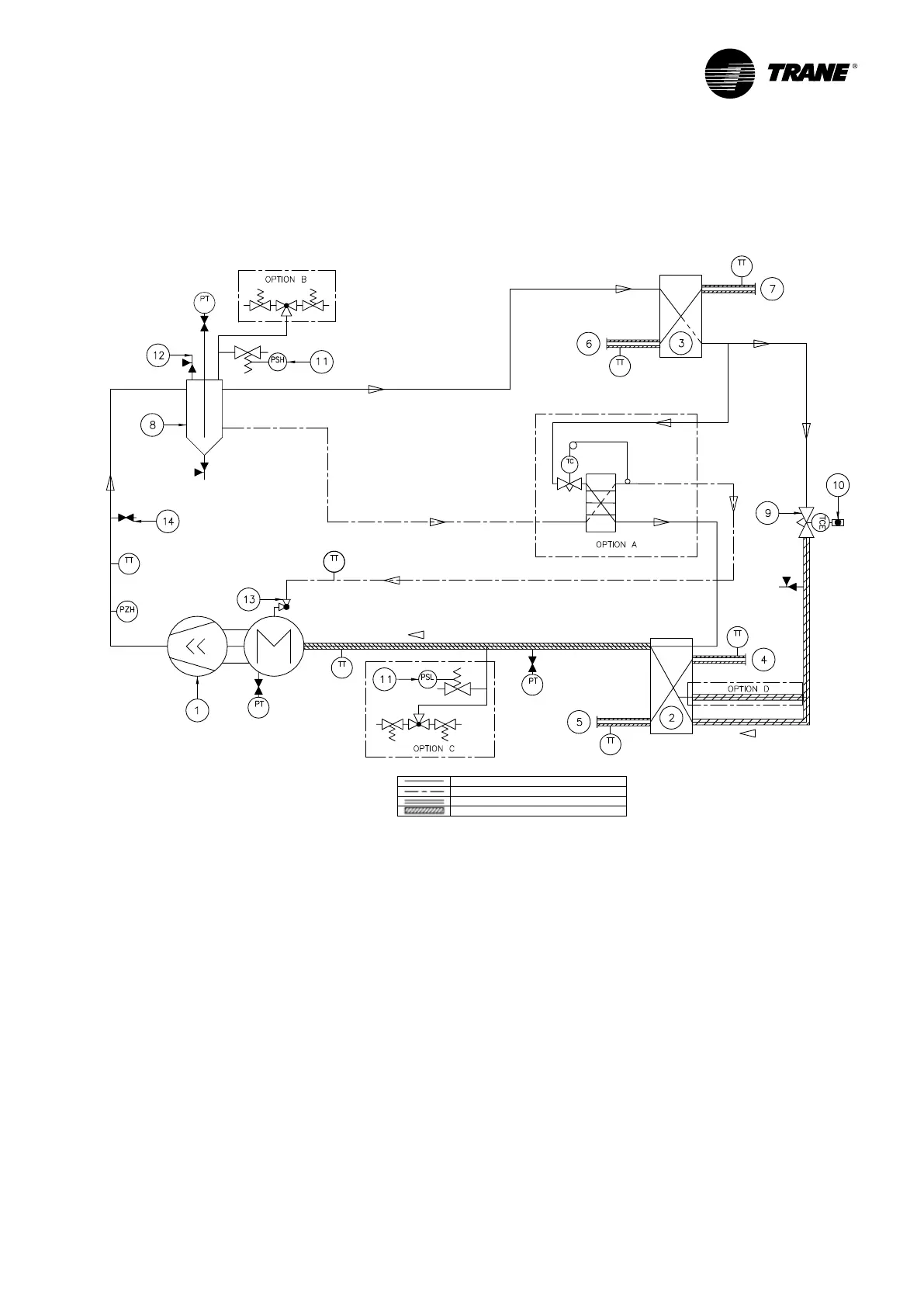
Refrigerant flow diagram
Refrigerant flow diagram for unit is supplied with drawing package with unit order.
Figure 6 – Example of typical refrigerant flow diagram
1 = Screw compressor
2 = Brazed plate evaporator
3 = Brazed plate condenser
4 = Evaporator water inlet connection
5 = Evaporator water outlet connection
6 = Condenser water inlet connention
7 = Condenser water outlet connention
8 = Oil separator
9 = Electric expantion valve
10 = Sight glass
11 = Relief valve
12 = Service valve
13 = Oil service valve
14 = Schraeder valve
REFRIGERANT LINE
OIL LINE
CHILLED HEATED WATER LINE
INSULATION
PT = Pressure transducer
PSH = High pressure relief valve
PSL = Low pressure relief valve
PZH = High pressure switch
TT = Temperature sensor
TCE = Electronic expansion valve
TC = Thermostatic expansion valve
LT = Liquid level sensor
Option A = Auxiliary oil cooler
Option B = Dual relief valve for discharge side
Option C = Single or dual relief valve for suction side
Option D = Liquid line according to evaporator size
Operating Principles Mechanical
 Loading...


