RLC-SVX023A
42
4 UNT-PRC002-GB
Technical Data
FWD 08 12 20 30 45
Power supply (V/Ph/Hz) 230/1/50
Capacities
Cooling capacity on water (1) (kW) 5,2 8,3 15 18,8 30,1
Heating capacity on water (2) (kW) 6,3 11,9 18,9 20,9 38,2
Fan motor (type) 2 x direct drive centrifugal
Fan power input (3) (kW) 0,23 0,46 0,65 1,04 1,51
Current amps (3) (A) 1,1 2,2 3,1 4,7 5,5
Start-up amps (A) 3,2 5,5 9,3 14,1 16,5
Air flow
minimum (m
3
/h) 490 980 1400 1800 2700
nominal (m
3
/h) 820 1650 2300 3000 4500
maximum (m
3
/h) 980 1970 2600 3600 5400
Main coil
Water entering/leaving connections (type) ISO R7 rotating female
(Dia) 3/4" 3/4" 1 1/2" 1 1/2" 1 1/2"
Electric heater (accessory for blower only)
Electric power supply (V/Ph/Hz) 230/1/50 230/1/50 or 400/3/50 400/3/50 400/3/50 400/3/50
Heating capacity (kW) 2/4 8 10 12 12
Hot water coil (accessory for blower only)
Heating capacity (4) (kW) 6,3 12 17,4 22,4 34,5
G2 filter (filter box accessory)
Quantity 2 2 2 2 2
Dimensions ( LxWxth) (mm) 386x221x8 486x271x8 586x321x8 586*421*8 586*621*8
G4 filter (filter box accessory)
Quantity - 2 2 2 2
Dimensions ( LxWxth) (mm) - 486x264x48 586x314x48 586*414*48 586*614*48
Condensate pump (accessory) (type) Centrifugal
Water flow - lift height (l/h - mm) 24 - 500
Not available for FWD30 and FWD45
Sound level (L/M/H speed)
Sound pressure level (5) (dB(A)) 36/40/43 38/41/44 46/50/53 47/52/57 47/52/58
Sound power level (5) (dB(A)) 46/50/53 48/51/54 56/60/63 57/62/67 57/62/68
Unit dimensions
Width x Depth (mm) 890 x 600 1090 x 710 1290 x 820 1290 x 970 1290 x 1090
Height (mm) 250 300 350 450 650
Shipped unit dimensions
Width x Depth (mm) 933 x 644 1133 x 754 1333 x 864 1333 x 1008 1333*1133
Height (mm) 260 310 360 460 660
Weight (kg) 32 46 61 76 118
Colour galvanised steel
Recommended fuse size
Unit alone (aM/gI) (A) 8/16 8/16 8/16 8/25 8/25
Unit with electric heater (gI) (A) 16 (2kW),25 (4kW) 40 (230V),3*16 (400V) 3*20 3*25 3*25
(1) Conditions: Water entering/leaving temperature: 7/12 °C, Air inlet temperature 27/19°C DB/WB - Nominal air flow
(2) Conditions: Water entering/leaving temperature: 50/45 °C, Air inlet temperature 20°C DB - Nominal air flow
(3) At high speed with nominal air flow.
(4) Water entering/leaving temperature 90/70 °C, air inlet temperature 20 °C DB, Nominal air flow.
(5) A rectangular glass wool duct 1m50 long is placed on the blower.The measurement is taken in the room containing the blower unit.
Heat exchanger operating limits:
FWD:
*water temperature: max 100° C
*absolute service pressure: min 1 bar/max 11 bars
Accessories - Hot water coil:
*water temperature: min. +2° C/max. 100° C
*absolute service pressure: min 1 bar/max 11 bars
Maintenance Procedures
Table 6 - POE Oil Properties
Description Acceptable Levels
Moisture content less than 300 ppm
Acid Level
(mg KOH/g)
less than 0.5 TAN
Running the chiller at minimum load is the best for the quickest return of oil to the separator and sump. The machine
still needs to sit for approximately 30 minutes before the level is taken. At minimum load, the discharge superheat
should be highest. The more heat in the oil as it lays in the sump, the more refrigerant will boil off in the sump and
leave more concentrated oil. The oil level in the oil sump can be measured to give an indication of the system oil
charge. Follow the procedures below to measure the level.
1. Run the unit fully unloaded for approximately 20 minutes.
2. Cycle the compressor off line.
Oil Level Check
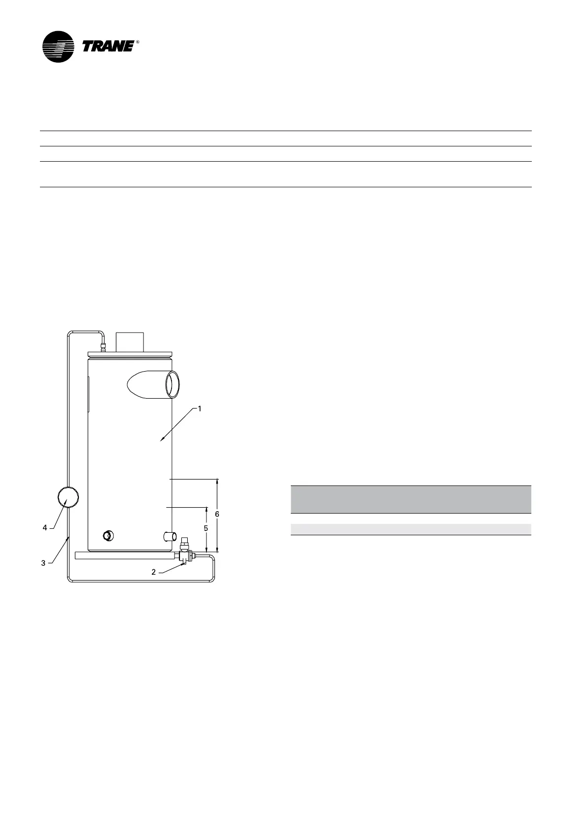
Figure 9 – Determining oil level in the oil separator
1 = Oil separator
2 = Valve
3 = 1/4” refrigeration hose
4 = Sight glass
5 = Minimum oil level
6 = Maximum oil level
How to measure the oil level:
1. Use the oil drain valve (bottom side) and the
service valve on the oil separator (top side). This
measurement can be made, when the circuit is not
running. Note: the bottom plate of the oil separator is
approximately 25mm thick.
2. The initial oil charge should be approximately at the
level in of the above chart. This is the approximate
oil level if all the oil is in the oil lines, filter, and oil
sump, and the unit is in vacuum so that there is no
refrigerant dissolved in the oil.
After the unit has run for a while, the oil level in the
sump can vary greatly. However, if the unit has run
‘normal’ conditions for a long time, the minimum and
maximum oil levels should correspond to values shown
in below table. However excessive oil in the system will
deteriorate the evaporator approach temperature.
Oil
separator
size
Compressors type
Min. oil
level (mm)
Max. oil
level (mm)
8” “M” type 50 mm 180 mm
10” “N” type 50 mm 140 mm
The field charging procedure depends on the
circumstances that resulted in the need for oil charge.
1. Some services procedures may result in loss of
small quantities of oil that must be replaced (oil
analysis, compressor filter replacement, re-tubing the
evaporator, and so forth).
2. Additionally, some maintenance procedures
may result in virtually all the oil being removed
(compressor motor burn or total removal of the charge
to trouble shoot a unit).
3. Finally, leaks may result in a loss of oil that must be
replaced.
Oil charging data.
The oil quantity is written on the nameplate of the unit.
 Loading...


