WSHP-SVX01Y-EN
47
Table 37. Ducted filter opening size GEH/V
(continued)
Unit Size
A (in.) B (in.) C (in.)
GEVG 006-
012 16.5 14.25
6.6
GEVG 015-
018 19.0 16.25
GEVG 024-
030 20.5 17.25
GEVG 036-
042 23.5 18.25
GEVG 048-
060 30.0 20.25
NNoottee:: All dimensions in inches. EXVG/DXVG
dimensions are for accessory 2 or 4" Filter Rack.
Dual Filtration (GEH 0.5 to 5 ton)
NNoottee:: The dual-filtration design is typically used in a
free-return application.
The horizontal, GEH model, allows the installer
flexibility in design applications such as a dual filtration
option. With the dual filtration design, the unit will
contain a lower static which translates into a decrease
in filter maintenance. For installation of a dual filtration
accessory for the GEH model, verify that an extra set of
return-air filter racks and filter have been ordered from
the factory. This accessory will be shipped separate
from the unit, and should be located in a separate box
than the unit.
1. Remove the return-air side panel from the GEH unit.
This panel is held in place by screws.
2. Install the top/bottom filter rack at the new opening.
The 1/2 (25.4 mm/50.8 mm) adjustable filter rack is
held in place with four screws that once held the
panel.
3. Install the 1/2 (25.4 mm/50.8 mm) filter.
Sound Attenuation Pad
For sound-sensitive installations, a vibration pad (field
provided) should be placed beneath the horizontal or
vertical equipment. For the horizontal unit, the pad
should be approximately twice the size of the unit foot
print. For the vertical unit, the pad should be 0.5 in.
(12.7 mm) thick, and equal to the overall unit foot print.
Hanging the Horizontal Unit
WWAARRNNIINNGG
PPrrooppeerr SSttrruuccttuurraall SSuuppppoorrtt RReeqquuiirreedd!!
FFaaiilluurree ttoo eennssuurree pprrooppeerr ssttrruuccttuurraall cceeiilliinngg ssuuppppoorrtt
ccoouulldd rreessuulltt iinn uunniitt ffaalllliinngg ffrroomm iittss llooccaattiioonn wwhhiicchh
ccoouulldd rreessuulltt iinn ddeeaatthh oorr sseerriioouuss iinnjjuurryy..
CCeeiilliinngg ssttrruuccttuurree mmuusstt bbee ssttrroonngg eennoouugghh ttoo
ssuuppppoorrtt tthhee wweeiigghhtt ooff tthhee uunniitt aanndd aannyy
aacccceessssoorriieess.. IIff uunnssuurree,, cchheecckk wwiitthh aa ssttrruuccttuurraall
eennggiinneeeerr..
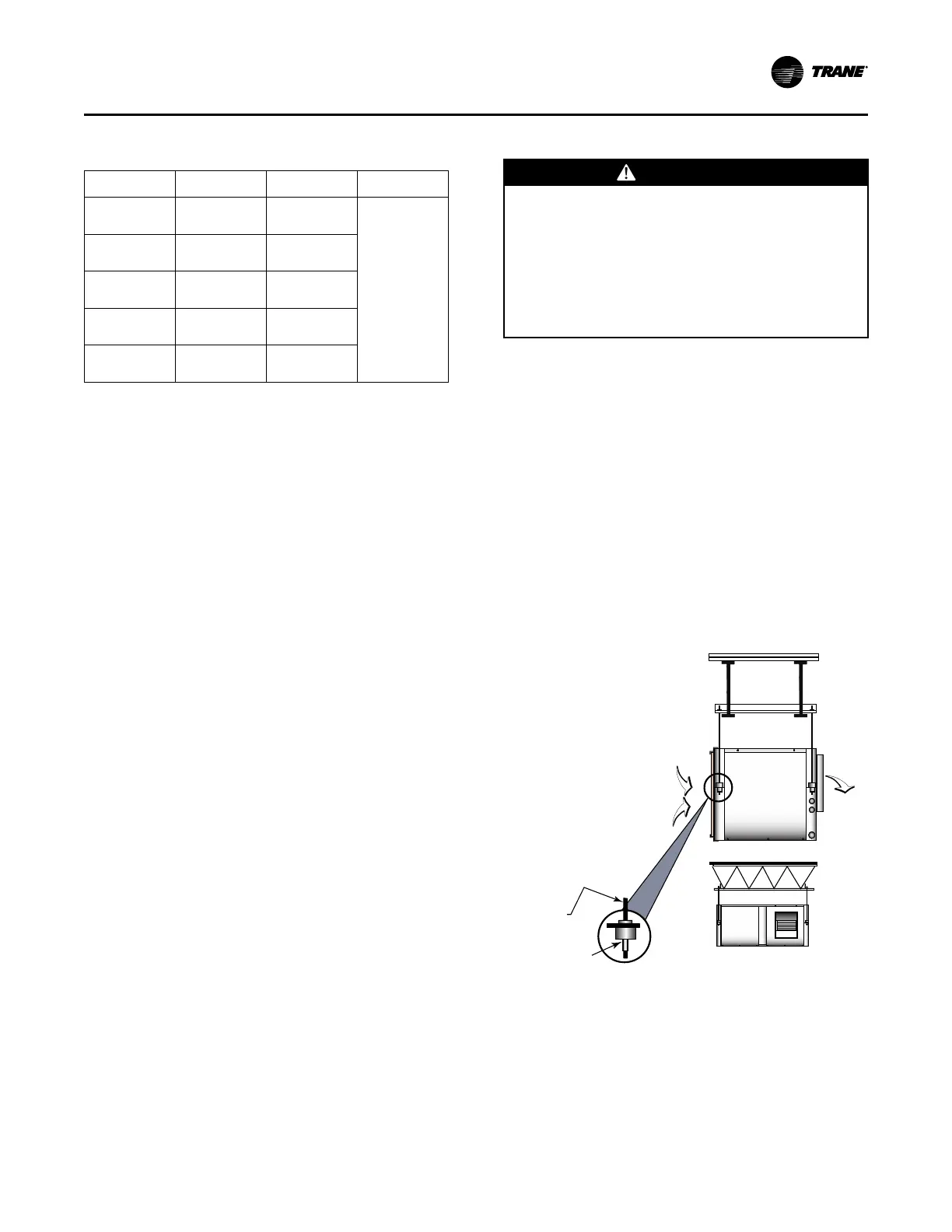
To hang the horizontal configuration (see the figure
below):
1. Install the hanging isolators (located in the return-
air section of the unit) into the four hanging
brackets.
2. Secure the equipment to a joist, concrete, etc. with
the use of 3/8 in. (9.7 mm) field provided (all-thread)
rod. Each corner should contain field provided nuts
and washers to complete the hanging installation.
3. Slope horizontal units in two directions. The unit
should contain a dual 0.25-12 pitch toward the drain
connection. This will insure proper drainage of the
unit. All plumbing to the unit should conform per
national and local codes and is the responsibility of
the contractor.
Figure 49. Hanging the unit
SUPPLY-AIR
3/8" ALL-THREAD
(BY OTHERS)
3/8" WASHER / NUT
(BY OTHERS)
RETURN-AIR
IInnssttaallllaattiioonn
 Loading...


