WSHP-SVX01Y-EN
57
Figure 61. Fan motor and sheave adjustment
1. Belt
2. Adjustment bolt and plate
3. Sheave
Vertical 0.5–5 tons - Units with Deluxe
24V or Tracer®® ZN524 controls
For vertical sizes GEVG 006-060, the ECM is
programmed for constant torque and delivers airflow
similar to a PSC motor while operating at a higher
efficiency.
Figure 62. ECM control box
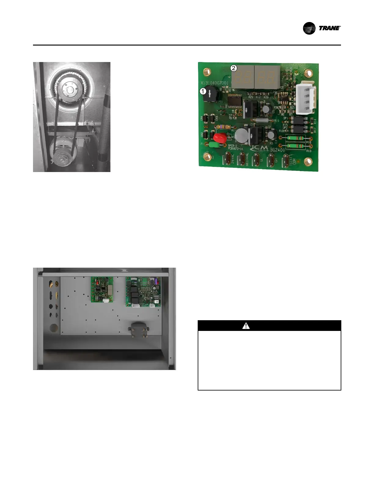
Figure 63. ECM control board
1. Potentiometer will be used to adjust the PWM
output
2. Seven segment display
Using a screwdriver, the potentiometer will be used to
adjust the PWM output from 20% to 100% PWM.
Increasing the PWM will increase the motor speed.
When setting the airflow for air balancing, the high-
speed terminal (GH) must have 24 Vac signal. This will
ensure that the PWM output will be adjusted for the full
load airflow.
The display will show the commanded motor speed
percentage. If running on low speed (GL), the low-
speed value will be displayed. If running in GH the
high-speed value will be displayed. If both GH and GL
input signals are present, the PWM output value will be
the GH value.
Waterside Economizer
Installation
WWAARRNNIINNGG
HHaazzaarrddoouuss VVoollttaaggee!!
FFaaiilluurree ttoo ddiissccoonnnneecctt ppoowweerr bbeeffoorree sseerrvviicciinngg ccoouulldd
rreessuulltt iinn ddeeaatthh oorr sseerriioouuss iinnjjuurryy..
DDiissccoonnnneecctt aallll eelleeccttrriicc ppoowweerr,, iinncclluuddiinngg rreemmoottee
ddiissccoonnnneeccttss bbeeffoorree sseerrvviicciinngg.. FFoollllooww pprrooppeerr
lloocckkoouutt//ttaaggoouutt pprroocceedduurreess ttoo eennssuurree tthhee ppoowweerr
ccaann nnoott bbee iinnaaddvveerrtteennttllyy eenneerrggiizzeedd.. VVeerriiffyy tthhaatt nnoo
ppoowweerr iiss pprreesseenntt wwiitthh aa vvoollttmmeetteerr..
IInnssttaallllaattiioonn
 Loading...


