RLC-SVX02G-E4
34
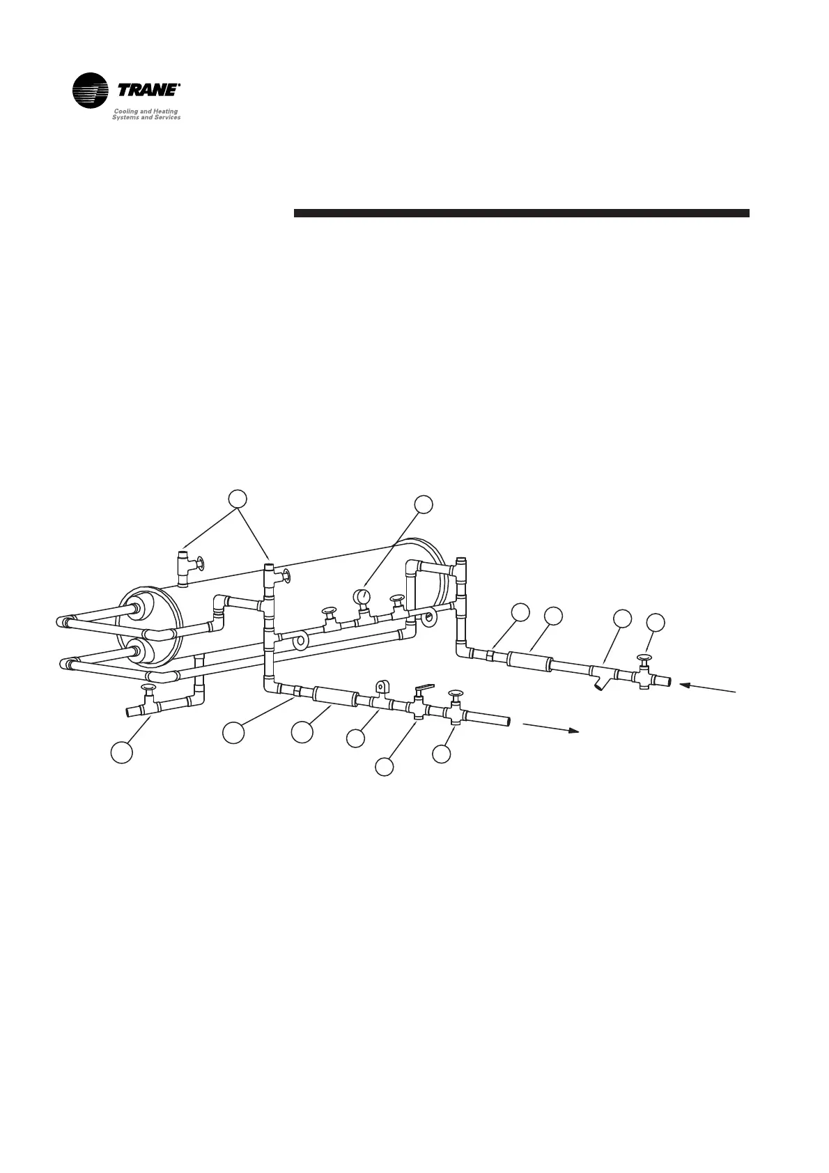
Installation - Mechanical
Water Pressure Gauges
Install field-supplied pressure
components as shown in Figure 5.
Locate pressure gauges or taps in a
straight run of pipe; avoid
placement near elbows, and so
forth. Be sure to install the gauges
at the same elevation on each shell
if the shells have opposite-end
water connections.
1
2
3
4
5
6
6
7
8
4
3
9
1. Vents
2. Valved Pressure Gauge
3. Union
4. Elastomeric Vibration Eliminator
5. Water Strainer
6. Gate Valve
7. Balancing Valve
8. Flow switch (optional)
9. Drain
Figure 5 – Suggested Piping for a Typical RTAC Evaporator
 Loading...