55
RLC-SVX02G-E4
Operating Principles
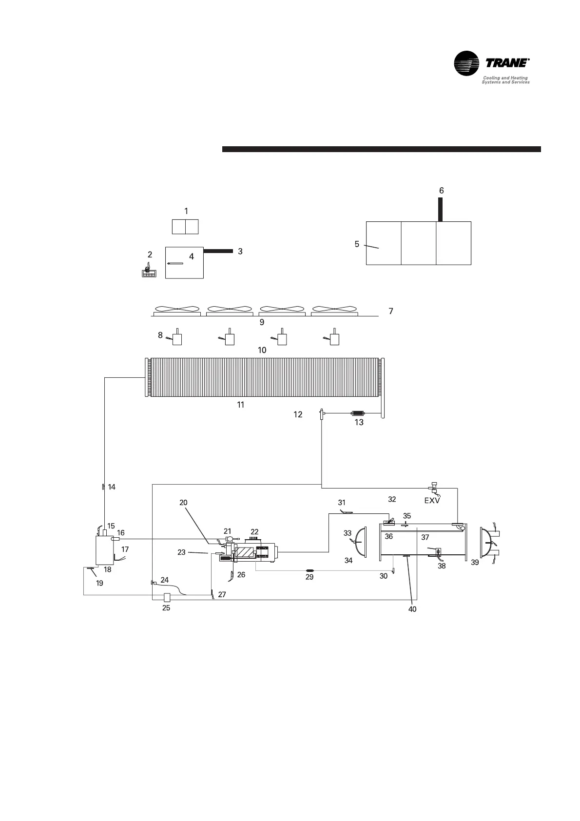
Figure 7 – System Schematic
1. Variable-Speed Fan Inverter
(optional)
2. EasyView (or DynaView) Interface
3. To Fans
4. Control Panel (Fans, Fuses)
5. Control Panel (Starters, Breakers,
Transformer)
6. To Compressor
7. Fan Deck
8. Inverter-Driven Motor
9. Fans
10. Fan Motors
11. Condenser Coil with Subcooler
12. Liquid-Line Isolation Valve
13. Liquid-Line Filter
14. Discharge Service Valve
15. Discharge Pressure Transducer
16. Relief Valve
17. Heater
18. Oil Separator
19. Oil Drain Valve
20. High-Pressure Cutout Load-Control
Solenoids
21. Discharge Isolation Valve
22. Compressor
23. Oil Line Shutoff Oil Filter
24. TXV
25. Oil Cooler (option)
26. Oil Pressure Transducer
27. Oil Temperature Sensor
29. Oil Return Line Filter
30. Oil Return Shutoff
31. Suction Pressure Transducer
32. Suction Isolation Valve (option)
33. Heater
34. Inlet Water Box, Inlet Water
Temperature
35. Relief Valve
36. Liquid Distribution System
37. Evaporator
38. Liquid Level Sensor
39. Outlet Water Box, Outlet Water
Temperature
40. Evaporator Service valves
 Loading...