16 BAS-SVN040B-EN
Installation
Step 6: Wire I/O
The field I/O wiring is specific for each application.
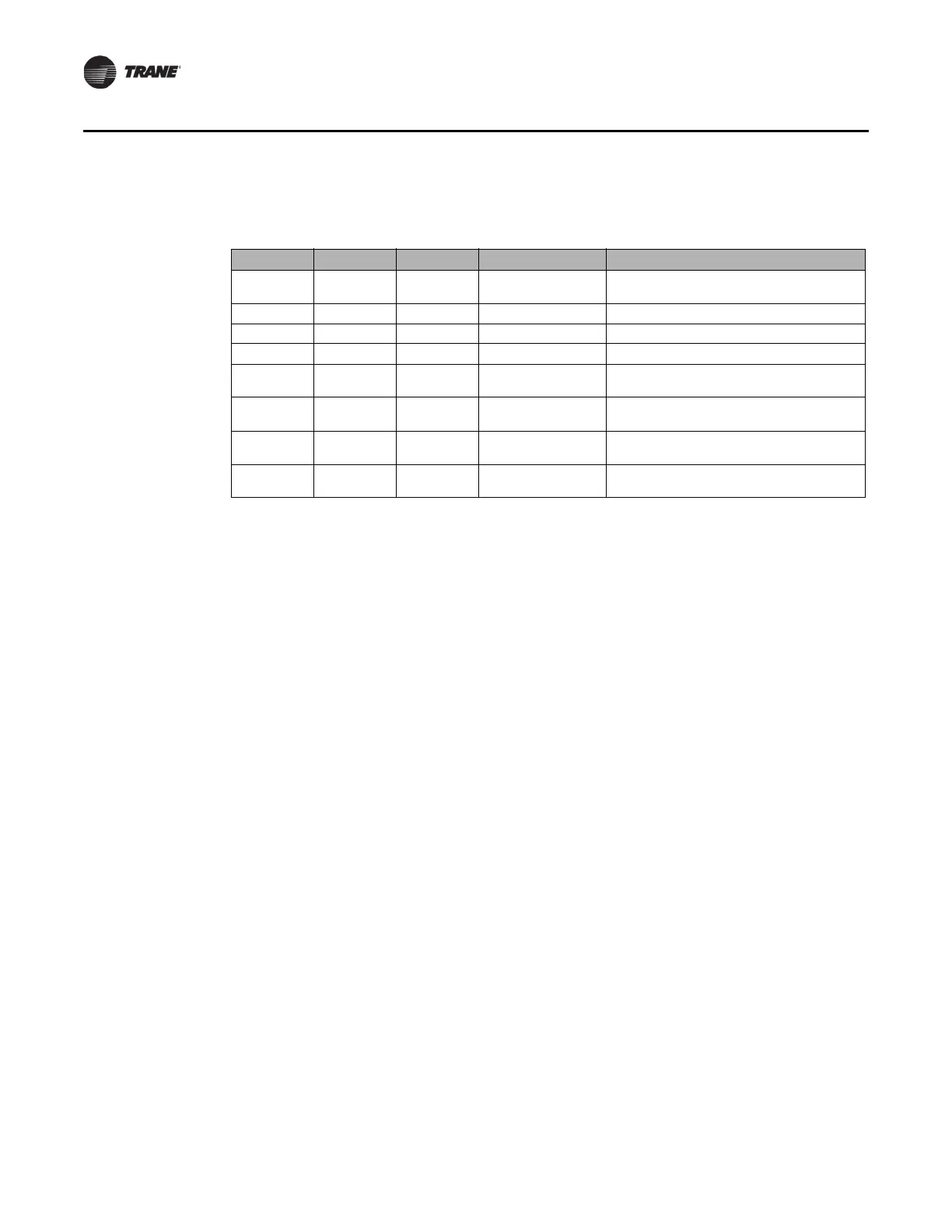
Module Rotary Dial Terminals Name Notes
XM30 01 UI/AO 1
Outside Air
Tempe
rature
Thermistor
XM30 01 UI/AO 2 N/A Not used
XM30 01 UI/AO 3 N/A Not used
XM30 01 UI/AO 4 N/A Not used
XM32 02 BO1 XM32 Binary Output 1
Must be wired as dry contact; used for lighting
output or o
ther (for example, exhaust fan)
XM32 02 BO2 XM32 Binary Output 2
Must be wired as dry contact; used for lighting
output or o
ther (for example, exhaust fan)
XM32 02 BO3 XM32 Binary Output 3
Must be wired as dry contact; used for lighting
output or o
ther (for example, exhaust fan)
XM32 02 BO4 XM32 Binary Output 4
Must be wired as dry contact; used for lighting
output or o
ther (for example, exhaust fan)
Step 7: Mount the Display
Note: The display is designed for conditioned indoor environments only. Mount the display where
occupants can access it for comfort/setpoint control and minor schedule modifications.
The display mounts to the wall using a VESA mount. The required VESA mounting bracket size is
75 mm x 75 mm
. A VESA mount is included with the display, but any standard VESA mount should
be acceptable. Brand, tilt, swivel and any other features are acceptable.
1. Select the wall space to mount the display. Mounting constraints are
as follows:
• The di
splay must be powered continuously, so mount it near an electrical outlet or near the
enclosure with the accessory outlet.
• The display commun
icate
s to the Concierge Controller using either Wi-Fi or Ethernet cable
connection. Use standard Wi-Fi guidelines to select the display location.
• The display should be accessible for
an
y users that are allowed to make adjustments using
the display.
2. Disassemble the VESA mount.
3. Install the wall section onto the
wall.
4. Install
the display section of the VESA mount onto the display enclosure using the four (4)
screws included with th
e VESA mount.
5. Re-assemble the VESA mount so the display is now on the wall.
6.
For ease of initial setup, connect an Ethe
rnet cable between the display and Concierge
Controller’s Ethernet Port 2. Later, set up a Wi-Fi router or put both the display and Concierge
Controller on the customer’s network.
7. If mounted near the enclosure, plug the display into the
accessory
outlet in the enclosure.
 Loading...

