8 BAS-SVN040B-EN
Installation
Step 4: Install the UC210 Bypass Damper and Air-Fi® Wireless
If required for this site, install the UC210 Bypass Damper. See the installation documentation. The point list
below is for your convenience.
Table 3. I/O points
Location Function
Pressure Input Duct Static Pressure Local
AI3/DAT Discharge Air Temperature (Optional)
Actuator Damper Actuator
Note: Ensure Air-Fi® Wireless and zone sensors are addressed per the submittal.
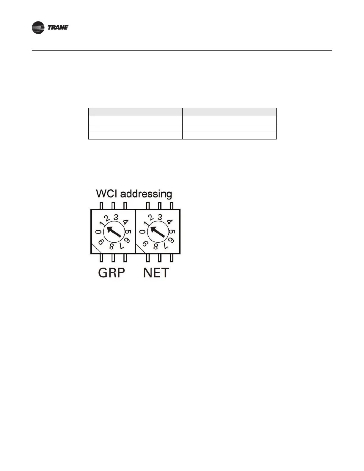
Addressing of the Wireless Communication Sensors (WCS) and Wireless Communication Interface
(WCI) determines which devices can co
mmunicate on an Air-Fi® network. On all WCS and WCI, the
GRP and NET are set at 1 and 1. When installing, confirm that these remain at 1 and 1.
Figure 2. Air-Fi® addressing
On unit controllers, such as rooftop units, VAV boxes, and bypass dampers, set the rotary address
settings to unique numbers. Set the first to 002, and so on. It's helpful to be sequential and not to
skip numbers; however, skipping numbers will not cause problems. Duplicate numbers will cause
communication problems.
 Loading...

