BAS-SVN040B-EN 7
Installation
Step 3: Install the UC400 2H/2C and Air-Fi® Wireless for Non-Trane
RTUs
If required for this site, install the UC400 2H/2C and Air-Fi® Wireless on non-Trane equipment. For
more information, see Tracer UC400 Pre-programmed for RTU or Heat Pump (X39641251-01B). The
point list below is for your convenience.
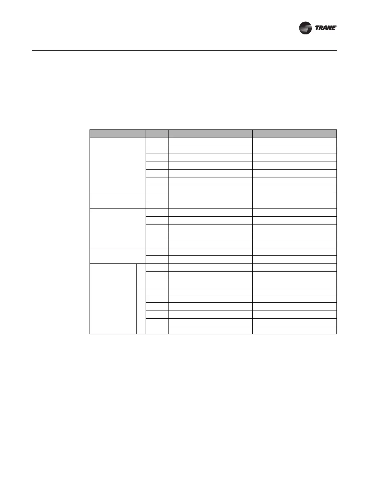
Table 2. Tracer® UC400 2H/2C RTU controller inputs and outputs
Inputs and Outputs Label Functions Descriptions
Analog Inputs
AI1 Space Temperature Sensor 10kΩ Thermistor
AI2 Space Te
mperature Setpoint 1kΩ Input
AI3 --
AI4 Discharge Air Temperature Sensor 10kΩ The
rmistor
AI5 Outdoor A
ir Temperature Sensor 10kΩ Thermistor
P1 -- --
P2 -- --
Unive
rsal Inputs
UI1 -- --
UI2 Occupancy Input (Binary) Open = Occupied, Closed = Unoccupied
Binary Inputs
BI1 Condensate Overflow Input Open = Normal, Closed = Alarm
BI2 Heat Pump Selection Input Open = DX, Closed = Heat Pump
BI3 Supply Fan Status Open = Off, Closed = On
BI4 -- --
BI5 -- --
Analog Outputs
AO1 -- --
AO2 -- --
Binary Outputs
Relays
BO1 Supply Fan Start Stop Command --
BO2 -- --
BO3 -- --
24VAC Triacs
BO4 Compressor 1 Command --
BO5 Compressor 2 Command --
BO6 Heat Stage W1 Command --
BO7 Heat Stage W2 Command --
BO8 Reversing Valve Command Off = Cooling, On = Heating
BO9 Auxiliary Heat Command --
Note: Ensure Air-Fi® Wireless and zone sensors are addressed per the submittal.
 Loading...

