Maintenance
28
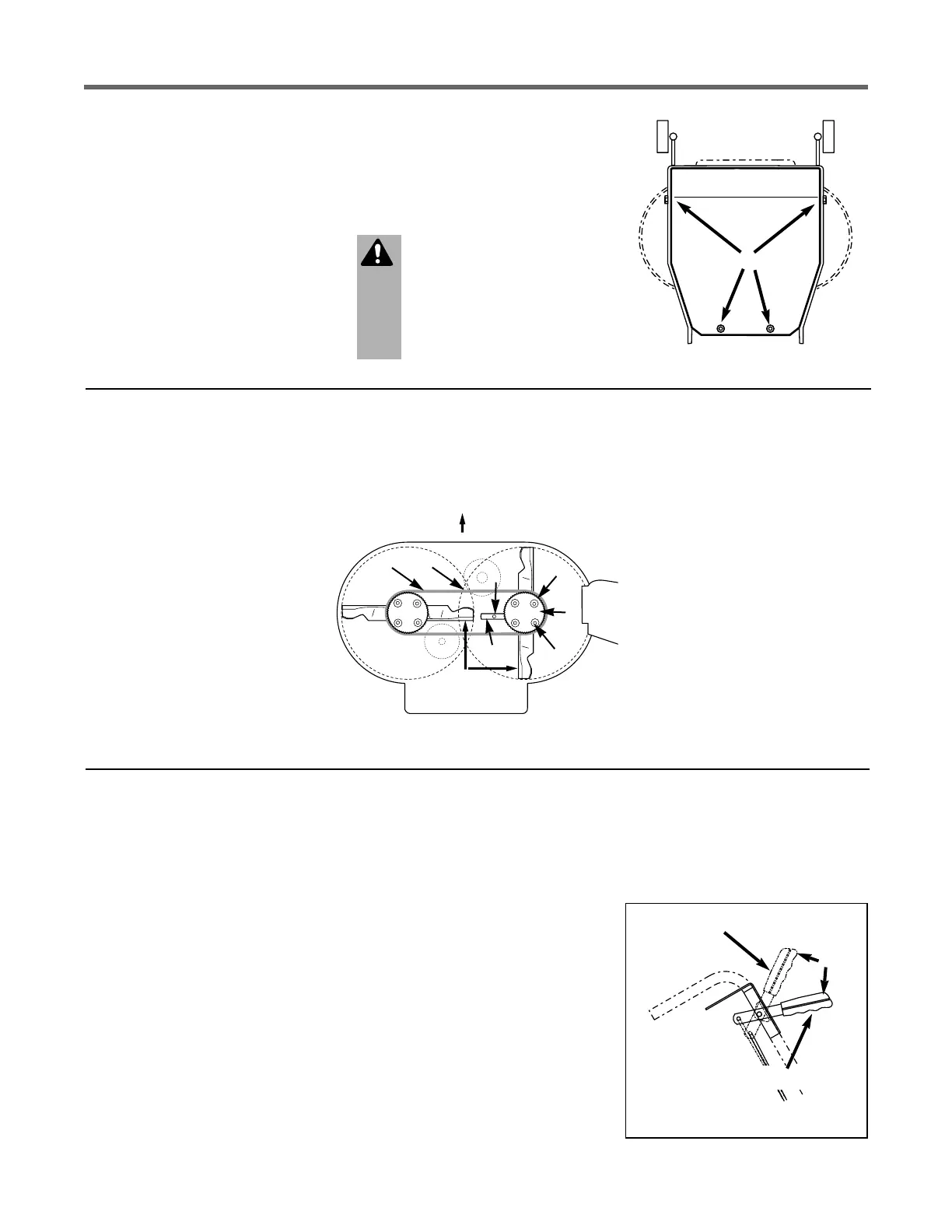
BELT COVER REMOVAL
The belt cover must be removed to
perform several maintenance pro-
cedures.
To Remove Belt Cover
1. Stop engine, wait for all parts
to stop moving, and disconnect
spark plug wire.
2. Remove four screws (R, Figure
5-5) and remove cover.
To Reinstall Belt Cover
1. Position belt cover in place.
2. Secure with four screws re-
moved earlier.
Figure 5-5: Belt cover removal.
R
BLADE SPINDLE BELT RE-
PLACEMENT
Follow this procedure to remove
and replace the blade spindle drive
belt (remove blade drive belt first;
see “Blade Drive Belt
Replacement” below).
1. Stop engine, wait for all parts
to stop moving and disconnect
spark plug wire.
2. Remove belt cover (see “Belt
Cover Removal”).
3. Align sight holes (O, Figure 5-
6) in pulley with spindle housing-
to-mower deck mounting bolts (L).
4. Loosen screw (J) and rotate arm
(K) to the rear.
5. Loosen four mounting bolts (L)
securing spindle housing (beneath
mower deck) to mower deck.
6. Slide spindle housing (with pul-
ley attached) toward center.
7. Replace belt (N) with new belt.
IMPORTANT: Set blades per-
pendicular (90°) to each other.
8. Rotate arm (K) to move spindle
housing and apply tension to belt.
Belt cogs and pulley grooves must
mesh together. When applying
moderate finger tension (8-12 lbs.),
belt should deflect approximately
1/2” (12.7 mm) at (P), midpoint of
deck.
9. Tighten bolts (L) to 15 ft.-lbs.
(20.3 Nm). Tighten screw (J).
10. Blades must not contact deck.
Check and readjust as needed.
11. Reinstall blade drive belt and
belt cover (removed earlier).
Figure 5-6: Blade Spindle Belt.
BLADE DRIVE BELT
REPLACEMENT
Follow this procedure to remove
and replace the blade drive belt.
An assistant will be needed.
To Remove Belt
1. Stop engine, wait for all parts
to stop moving, and disconnect
spark plug wire.
2. Disengage blade drive control
(Figure 5-7) by releasing all con-
trols on the mower.
3. Remove belt cover (see “Belt
Cover Removal”).
4. Loosen belt guides (B and C,
Figure 5-8).
5. Move flap bracket (N, Figure
5-8) out of the way by loosening
two screws (M).
6. Remove belt (A, Figure 5-8)
from around sheaves.
To Install Belt
1. Route belt (A, Figure 5-8)
around sheaves as shown.
2. Have an assistant hold down
Operator Presence Control and
then push the Blade Drive Control
forward until it latches in place
(Figure 5-7).
3. With the Blade Drive Control
lever engaged, adjust and tighten
belt guide (B) to 1/32 - 1/16"
away from tensioned belt. (Be
sure that belt does not contact belt
guide when belt is under tension.)
Secure belt guide (C) rotated into
position as shown in Figure 5-8.
Figure 5-7: Blade Drive Control.
RIGHT VIEW
Blade Drive Disengaged
Blade Drive Engaged
A
WARNING
Do not operate unit without
belt cover installed. Failure
to follow this instruction
could result in personal in-
jury or property damage.
4. Disengage Blade Drive Control.
5. Re-tighten two screws (M,
Figure 5-8) that secure flap
bracket (N).
6. Reinstall belt cover securely.
N
P
J
O
M
L
K
 Loading...