31
Connection diagrams
• The drawings are not intended to describe a complete system. It is up to the certified service technician to determine the neces-
sary components for and configuration of the particular system being installed (for example an additional surge protector).
• The drawings do not imply compliance with state or local code requirements or regulations. It is the certified service technician’s
responsibility to make sure that the installation is in full compliance with all state or local code requirements or regulations.
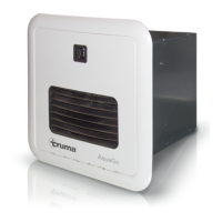
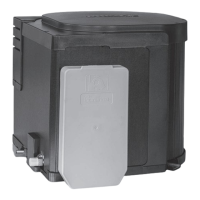
Model AquaGo® basic / AquaGo® comfort
Hot Water
Outlet
Cold Water
Inlet
Maximum pressure 65 psi (4.5 bar)
Inlet pressure 10.5 - 14 in. wc (26.2 - 34.9 mbar)
LP gas supply (propane only)
Top
Instant
Water Heater
C*
A*
B*
* Bypass kit for winterizing (not in scope of delivery)
Faucet 1 Faucet 2 Shower
Gas rear connection
Gas side connection
Fig. 18
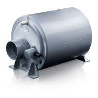
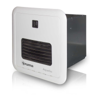
Model AquaGo® comfort plus
Circulation
Line Inlet
Cold Water
Inlet
Top
Hot Water
Outlet
Instant
Water Heater
C* D*
A*
E*
B*
* Bypass kit for winterizing (not in scope of delivery)
Drain Line
LP gas supply (propane only)
Gas side connection
Faucet 1 Faucet 2 Shower
Gas rear connection
Maximum pressure 65 psi (4.5 bar)
Inlet pressure 10.5 - 14 in. wc (26.2 - 34.9 mbar)
Fig. 19
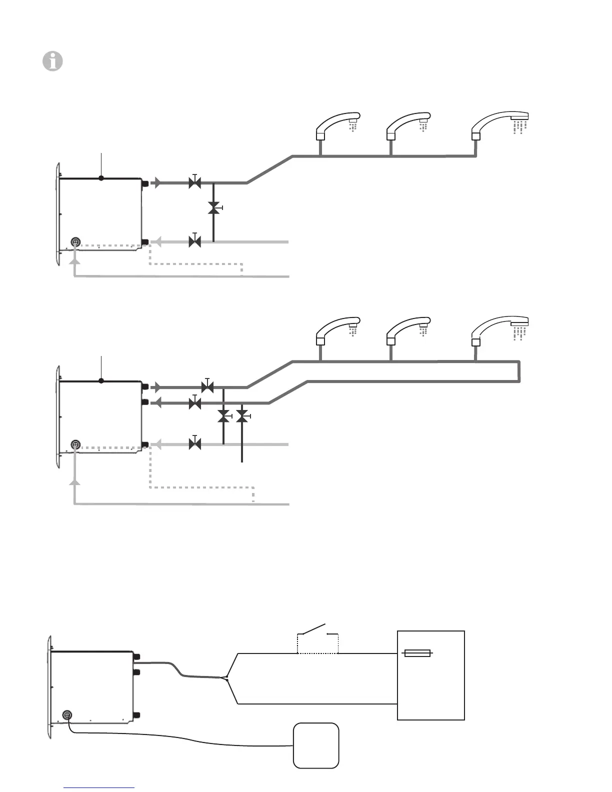
Electrical connection for all models
Maximum length of the power supply cable (including cables for the optional switch):
• for 16 AWG or 1.5 mm² MWG: max. 40 ft (12 m) (bidirectional)
• for 14 AWG or 2.0 mm² MWG: max. 66 ft (20 m) (bidirectional)
12 V DC
Ripple < 1 V
pp
12 V DC
Power
Supply
Instant
Water Heater
+
+
-
-
7.5 A
Switch ON - OFF
(Rating: ≥ 7.5 A)
Optional:
* only AquaGo® Comfort and
AquaGo® Comfort Plus
Control
Panel * /
Diagnosis
Fig. 20
 Loading...