23
OVEN SYSTEMS
The Conveyor System
This section contains information about the
following components, as well as testing
procedures:
- G
ear Drive (Conveyor Motor)
- G
ear Drive (Conveyor Motor) Speed
Contr
oller (CMSC)
G
ear Drive (Conveyor Motor)
The conveyor motor is a 1610 RPM, 3-phase
motor with a built-in H
all E
ffect Sensor. The
speed of the conv
ey
or motor is controlled by the
v
oltage fr
equency applied to the windings from
the CMSC.
The H
all Effect Sensor sends a DC
pulse back to the contr
ol boar
d to v
erify motor
speed.
The contr
ol boar
d uses these pulses to
determine the output DC v
oltage to the
CMSC.
Single-belt HhC 2020 ovens contain one gear
drive. Dual-belt ovens contains two gear drives.
T
esting Procedure
1.
Disconnect line voltage from the unit.
2.
T
ake a resistance reading of the motor
windings and use F
igur
e 33 to v
erify that
the r
esistance r
eadings ar
e correct.
3.
I
f the r
esistance r
eadings are correct,
r
econnect the motor wiring and then apply
line v
oltage to the unit and check for
voltage applied to the motor windings.
4.
If no voltage is present, ensure the CMSC is
operating pr
operly (see below).
5. If CMSC is operating properly, inspect the
wir
e harness for damage or shorts.
6.
If the wire harness is intact and undamaged,
and the CMSC is operating pr
operly, the
gear drive is damaged or defective and must
be r
eplaced.
G
ear Dr
ive (Conveyor Motor) Speed
C
on
troller (CMSC)
The CMSC converts single-phase line voltage to
a thr
ee-phase output, and contr
ols the speed of
the gear driv
e via fr
equency output. The CMSC
r
eceiv
es an input voltage (0-10 VDC) from the
control board and adjusts the frequency output
to the gear drive.
Testing Procedure
WARNING: Capacitors within the CMSC
can retain charge after power is removed.
Exercise extreme caution when handling the
terminals.
WARNING: DO NOT connect incoming
AC power to output terminals U, V, or W.
This will seriously damage the Conv
eyor
M
otor S
peed Controller.
1.
E
nsur
e that no faults appear on the display
of the CMSC during o
v
en operation.
The
control will display the frequency output if
the system is operating correctly.
2. Check the input voltage on terminals L1 &
L2 (200-240
VAC) and the DC voltage
input on terminals 0V & AI (0.1-10
VDC).
3.
I
f no input voltage is present, inspect the
wire harness for damage or shorts (pages
37-38).
4. If DC control voltage is not present, check
v
oltage output at I/O board. If no voltage is
pr
esent at the I/O board, replace the board.
J10-A13 to J9-C6 = front belt
J10-A14 to J10-A6 = r
ear belt.
5. Check ohms of motor (Figure 33).
6.
If wire harness is intact and undamaged,
the CMSC is damaged or defective and
must be replaced.
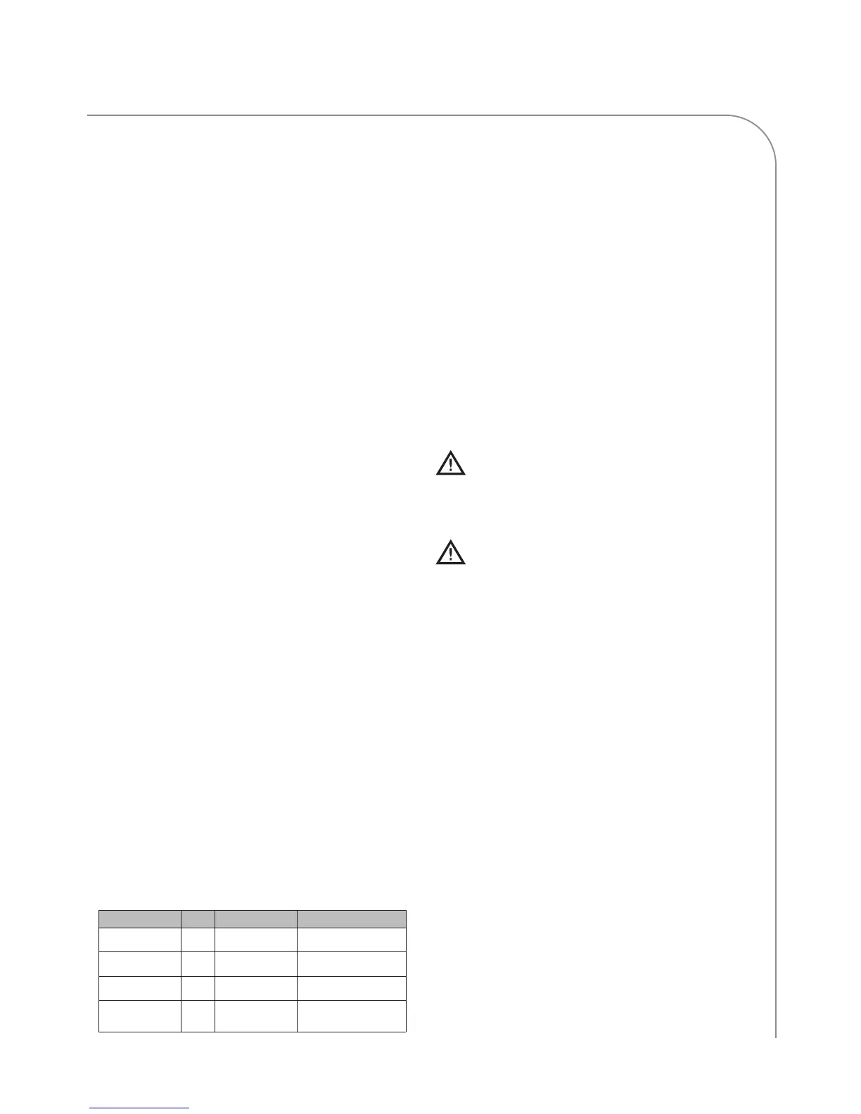
To From Description Expected Resistance
White G
rey
W
inding (A-B)
215-217 W
White Black Winding (A-C)
215-217 W
Grey Black Winding (B-C)
215-217 W
White, Grey, or
Black
G
reen
Windings to
chassis
O
pen
Figure 33: Conveyor Motor Ohm Chart
 Loading...