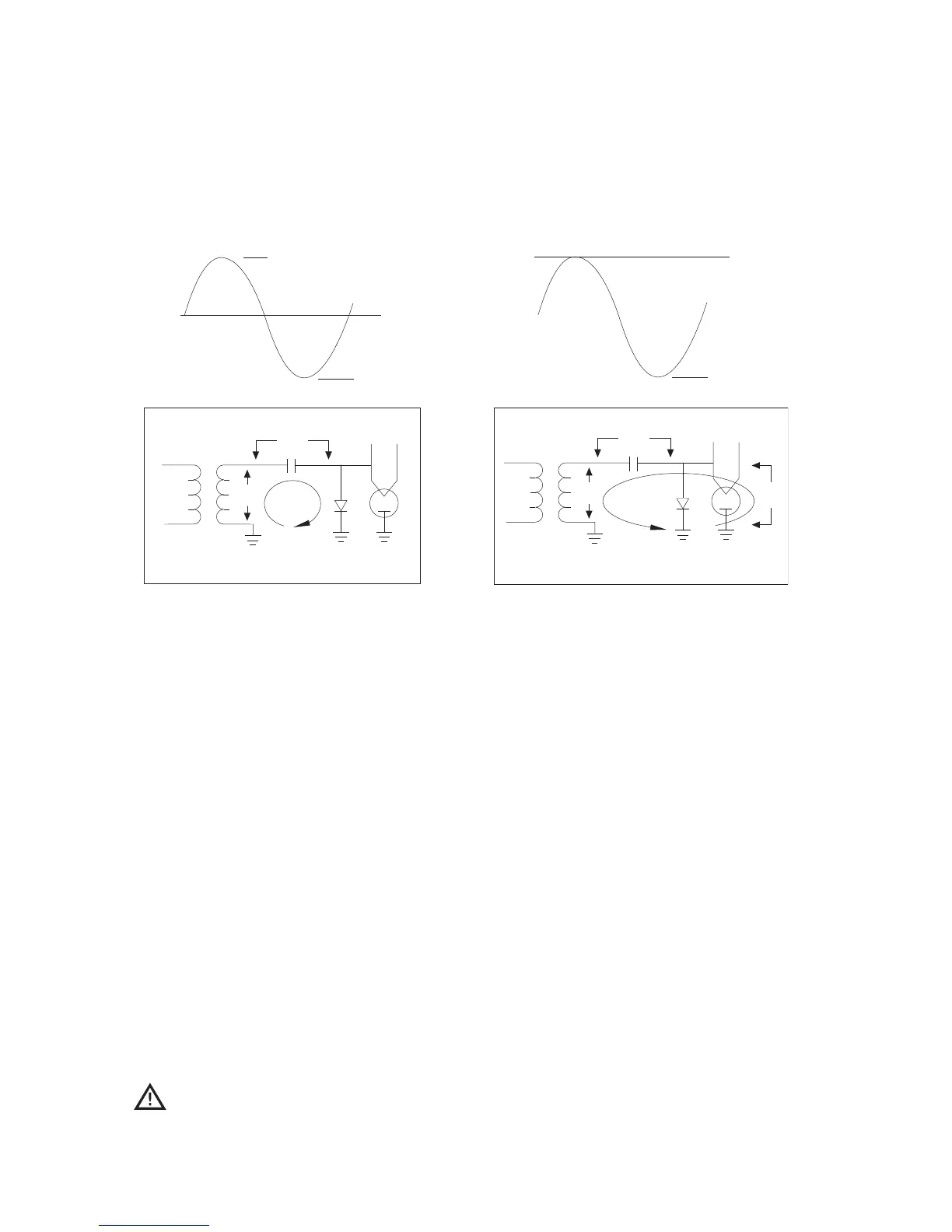
FIGURE 19: Voltage Doubler Circuit Theory of Operation
VOLTAGE DOUBLER THEORY OF OPERATION
Figure 19
1.
The high-voltage transformer steps up the input
voltage to approximately 2400 volts peak (4800
volts peak to peak).
2.
The high-voltage capacitor charges to 2400 volts
on the positive going voltage via the high volt
-
age diode’s conduction.
3. The high-voltage transformer plus the charged
high-voltage capacitor supply down to
-4800
volts to the magnetron when the voltage goes
negative. (high-voltage diode is back biased.)
4. The magnetron converts negative input voltage
(and current) to RF energy at 2450 MHz.
WARNING
:
Do not attempt to measure
these voltages.
MICROWAVE SYSTEM PARTS
Figures 20 and 21
11.
NGC-3062-1 HV Transformer (2 per oven, 1
per kit) - USA, Mexico, Brazil,
S. Korea
NGC-3062-2
HV Transformer (2 per oven, 1
per kit) - Europe, Asia, Pacific,
Australia, UK, Ireland
NGC-3062-3 HV Transformer (2 per oven, 1
per kit) - Japan
12. NGC-3020 High Voltage Capacitor (2 per
oven, 1 per kit) - USA, Mexico,
Brazil, S. Korea
NGC-3020-2
High Voltage Capacitor (2 per
oven, 1 per kit) - Europe, Asia,
Pacific, Australia, UK, Ireland,
Japan 50 Hz
100207
High Voltage Capacitor (2 per
oven, 1 per kit) - Japan 60 Hz
THE MICROWAVE SYSTEM
26
 Loading...