SARA-R4/N4 series - System Integration Manual
UBX-16029218 - R11 Design-in Page 111 of 157
2.6.5.2 Guidelines for DDC (I
2
C) layout design
The DDC (I
2
C) serial interface requires the same consideration regarding electro-magnetic interference as
any other digital interface. Keep the traces short and avoid coupling with RF line or sensitive analog inputs,
since the signals can cause the radiation of some harmonics of the digital data frequency.
2.7 Audio
2.7.1 Guidelines for Audio circuit design
☞ Audio is not supported by “00”, “01”, “02” and “52” product versions: the I
2
S interface pins should not
be driven by any external device.
2.8 General Purpose Input/Output
2.8.1 Guidelines for GPIO circuit design
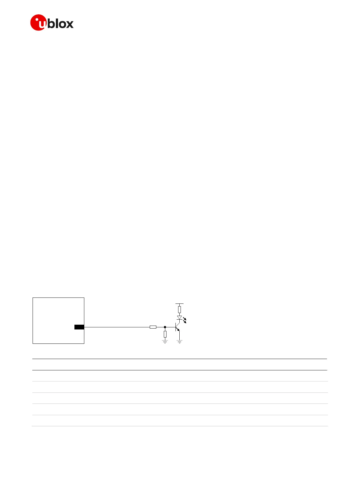
A typical usage of SARA-R4/N4 series modules’ GPIOs can be the following:
Network indication provided over GPIO1 pin (see Figure 53 / Table 36 below)
GNSS supply enable function provided by the GPIO2 pin (see section 2.6.5)
GNSS Tx data ready function provided by the GPIO3 pin (see section 2.6.5)
Module operating status indication provided by a GPIO pin (see section 1.6.1)
SIM card detection provided over GPIO5 pin (see Figure 39 / Table 28 in section 2.5)
SARA-R4/N4
GPIO1
R1
R3
3V8
Net work Indicat or
R2
16
DL1
T1
Figure 53: Application circuit for network indication provided over GPIO1
Part Number - Manufacturer
10 k Resistor 0402 5% 0.1 W
47 k Resistor 0402 5% 0.1 W
820 Resistor 0402 5% 0.1 W
LTST-C190KRKT - Lite-on Technology Corporation
Table 36: Components for network indication application circuit
 Loading...


