SARA-R4/N4 series - System Integration Manual
UBX-16029218 - R11 System description Page 30 of 157
1.6 System function interfaces
1.6.1 Module power-on
When the SARA-R4/N4 series modules are in the not-powered mode (i.e. the VCC module supply is not
applied), they can be switched on as follows:
Rising edge on the VCC input pins to a valid voltage level, and then a low logic level needs to be set
at the PWR_ON input pin for a valid time.
When the SARA-R4/N4 series modules are in the power-off mode (i.e. switched off) or in the Power Saving
Mode (PSM), with a valid VCC supply applied, they can be switched on as follows:
Low pulse on the PWR_ON pin for a valid time period
The PWR_ON input pin is equipped with an internal active pull-up resistor. Detailed electrical characteristics
with voltages and timings are described in the SARA-R4/N4 series Data Sheet [1].
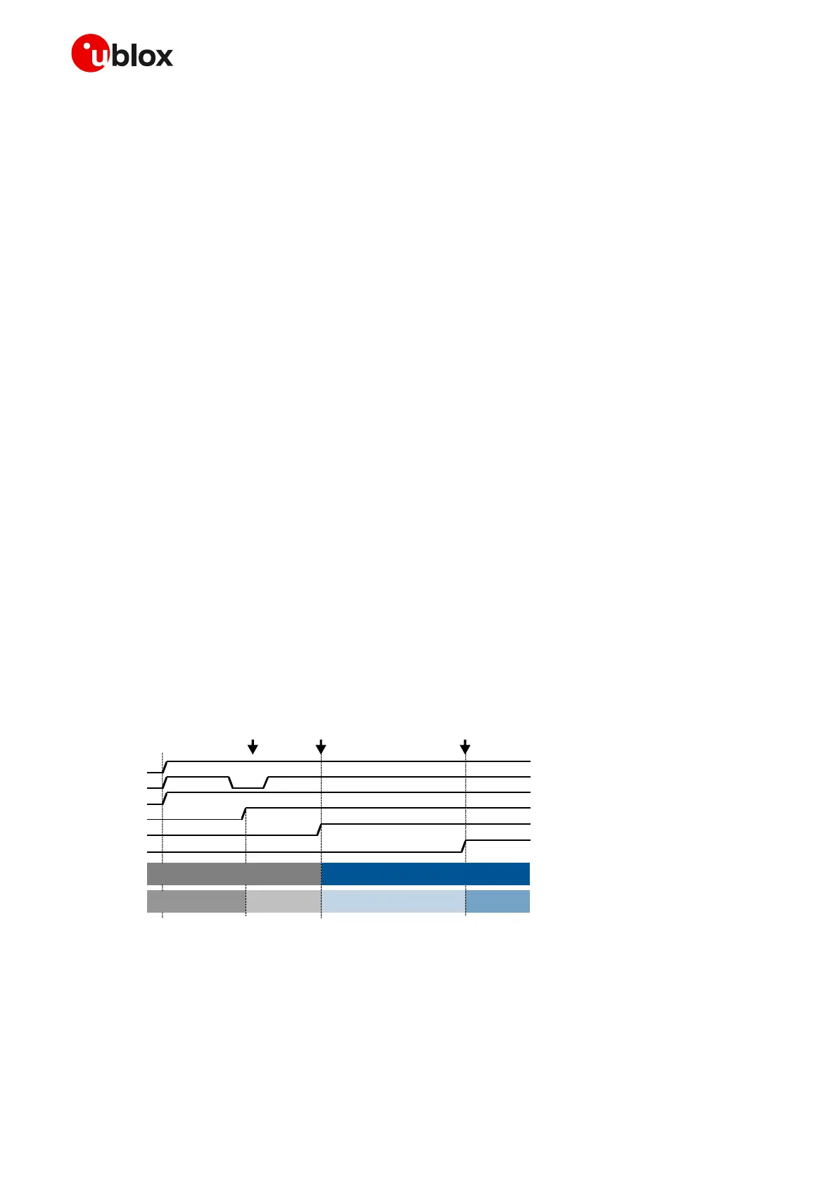
Figure 9 shows the module switch-on sequence from the not-powered mode, with following phases:
The external power supply is applied to the VCC module pins
The PWR_ON pin is held low for a valid time
All the generic digital pins are tri-stated until the switch-on of their supply source (V_INT).
The internal reset signal is held low: the baseband core and all digital pins are held in reset state. When
the internal reset signal is released, any digital pin is set in the correct sequence from the reset state to
the default operational configured state. The duration of this phase differs within generic digital
interfaces and USB interface due to host / device enumeration timings.
The module is fully ready to operate after all interfaces are configured.
VCC
PWR_ON
RESET_N
V_INT
Internal Reset
GPIO
System State
BB Pads State Operational
Internal Reset → Operational
Figure 9: SARA-R4/N4 series switch-on sequence description
☞ The Internal Reset signal is not available on a module pin, but it is highly recommended to monitor:
o the V_INT pin, to sense the start of the SARA-R4/N4 series module switch-on sequence
o the GPIO pin configured to provide the module operating status indication (see SARA-R4/N4 series
Commands Manual [2], AT+UGPIOC), to sense when the module is ready to operate
 Loading...


