SARA-R4/N4 series - System Integration Manual
UBX-16029218 - R11 Design-in Page 98 of 157
2.6 Data communication interfaces
2.6.1 UART interface
2.6.1.1 Guidelines for UART circuit design
Providing the full RS-232 functionality (using the complete V.24 link)
If RS-232 compatible signal levels are needed, two different external voltage translators can be used to
provide full RS-232 (9 lines) functionality: e.g. using the Texas Instruments SN74AVC8T245PW for the
translation from 1.8 V to 3.3 V, and the Maxim MAX3237E for the translation from 3.3 V to RS-232
compatible signal level.
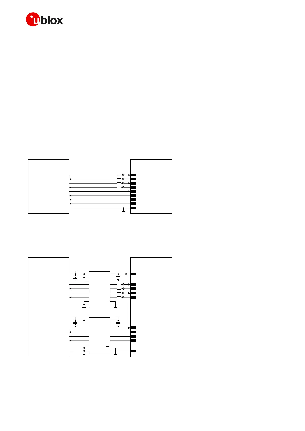
If a 1.8 V Application Processor (DTE) is used and complete RS-232 functionality is required, then the
complete 1.8 V UART of the module (DCE) should be connected to a 1.8 V DTE, as in Figure 40.
TxD
Application Processor
(1.8V DTE)
RxD
RTS
CTS
DTR
DSR
RI
DCD
GND
SARA-R4/N4
(1.8V DCE)
12
TXD
9
DTR
13
RXD
10
RTS
11
CTS
6
DSR
7
RI
8
DCD
GND
0Ω
TP
0Ω
TP
0Ω
TP
0Ω
TP
Figure 40: UART interface application circuit with complete V.24 link in DTE/DCE serial communication (1.8V DTE)
If a 3.0 V Application Processor (DTE) is used, then it is recommended to connect the 1.8 V UART of the
module (DCE) by means of appropriate unidirectional voltage translators using the module V_INT output
as 1.8 V supply for the voltage translators on the module side, as described in Figure 41.
4
V_INT
TxD
Application Processor
(3.0V DTE)
RxD
RTS
CTS
DTR
DSR
RI
DCD
GND
SARA-R4/N4
(1.8V DCE)
12
TXD
9
DTR
13
RXD
10
RTS
11
CTS
6
DSR
7
RI
8
DCD
GND
1V8
B1 A1
GND
U1
B3A3
VCCBVCCA
Unidirectional
Voltage Translat or
C1
C2
3V0
DIR3
DIR2 OE
DIR1
VCC
B2 A2
B4A4
DIR4
1V8
B1 A1
GND
U2
B3A3
VCCBVCCA
Unidirectional
Voltage Translat or
C3
C4
3V0
DIR1
DIR3 OE
B2 A2
B4A4
DIR4
DIR2
TP
0Ω
TP
0Ω
TP
0Ω
TP
0Ω
TP
Figure 41: UART interface application circuit with complete V.24 link in DTE/DCE serial communication (3.0 V DTE)
Flow control is not supported by ‘00’, ‘01’ and SARA-R410M-02B product versions, but the RTS input must be set low to use the UART on
‘00’ and ‘01’ versions. The DTR input must be set low to have URCs presented over UART on ‘00’, ‘01’ and ‘x2’ product versions.
 Loading...


