UTD2000 Series User Manual
17
2.1 Setting coupling channel
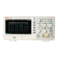
If the measured signal connected to the CH1 channel is a sinusoidal signal containing
DC component. If your press F1 to select as AC coupling, to set the CH1 into AC coupling
mode. Then the DC component of the measured signal is blocked. Waveform display is
shown in figure below.
Figure 2-1 Blocked DC Component of Signal
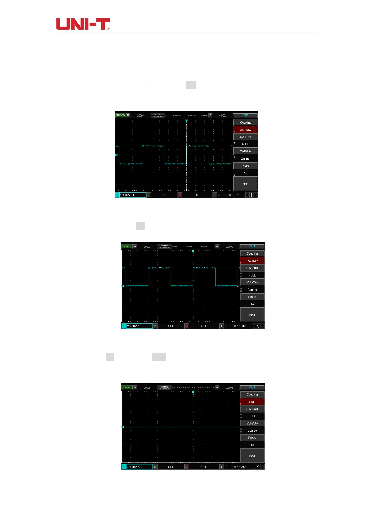
Press F1 to select as DC coupling, you should be able to see both the DC and AC
components of measured signals at CH1 channel as shown in figure below.
Figure 2-2 Simultaneous Display of Signal DC and AC Components
If you Press F1 to select as GND, to set CH1 to connect to the internal ground of the
instrument, both DC and AC components of the input signal are blocked. And, waveform
display is shown in figure below.
Figure 2-3 Simultaneous Blocking of Signal DC and AC Components
 Loading...


