UTD2000 Series User Manual
25
According to sin θ=A/B or C/D, θ is the angle difference of channels, the definition of A, B,
C, D is shown in figure above, so the angle difference is: θ=±arcsin (A/B) or θ=±arcsin
(C/D). If the elliptical axis lies on I, III quadrant, then the phase difference of angle should
lie on I, IV quadrant, that is within (0~π/2) or (3π/2~2π). If the elliptical axis lies on II、IV
quadrant, the phase difference of angle should be within (π/2~π) or (π~3π/2). Additonally,
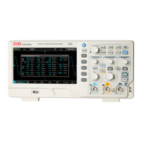
users can also figure out the frequency and phase relation between two signals according
to Lissajous figures below:
Figure 3-4 Common Lissajous Figures
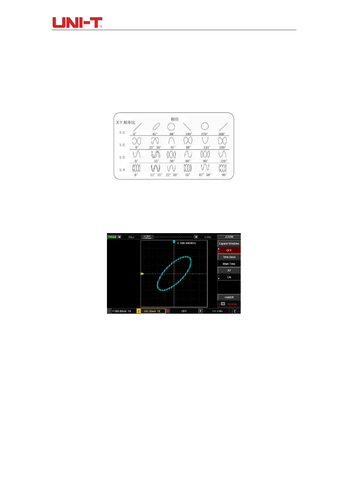
Only when CH1 and CH2 are used simultaneously can this method be adopted. After
selecting XY display mode, CH1 volatage is displayed on horizontal axis and CH2 voltage
is displayed on vertical voltage.
Figure 3-5 Waveform Display under XY Mode
Note: To ensure a better dispay effect of lissajous figures, the waveform display under
XY mode has a complete cycle at least. Below functions in XY display mode are
ineffective.
Cursor Measurement Mode
Reference or Mathematical Operation Waveform
Window Extension Function
Trigger Control
 Loading...


