Page 13
POWERING TECHNOLOGY
Manual No. MS0027-MAN rev. 4
guardian_access_3u_ms27-man-rev4-0817.indd
NOTE For details of FMP20.48 and FMP30.48C available only in APAC region please
see individual datasheets.
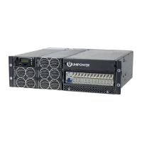
2.3 System Components
With the exception of the rectier modules the Guardian Access 3U system is delivered with
all components mounted according to the ordered conguration. The main components are
described below and in later chapters of this manual.
2.3.1 System Controller
The Guardian power system can be controlled by the ACC Extended or PCC controller.
The description and operation of these controllers is covered in separate manuals which
are available at:
ACC Extended: http://www.unipowerco.com/pdf/acc-man.pdf
PCC: http://www.unipowerco.com/pdf/pcc-man.pdf
2.3.2 DC Distribution Unit
The distribution unit includes congurable load breakers, battery breakers, a shunt for
battery current measurement and fuse alarms for load and battery breakers.
The distribution unit has no special operation other than switching the load and battery
breakers on and o. All trip states of breakers are supervised by measuring the voltage
drop across each breaker.
Breakers that are not connected to any load will not cause a breaker alarm even if they
are left open.
A battery fuse alarm may not be triggered instantly when a battery breaker is o. The
alarm is triggered only when the voltage drop between the system voltage and the battery
voltage is more than 1.5V. The interval that the voltage drop increases to 1.5V depends
on the battery status.
Due to a small leakage current (2.5-3mA) through the alarm circuit, the voltage measured
with a Digital Volt Meter (DVM) on an open breaker output will be nearly equal to the
rectier output voltage.
The distribution module has common “+Ve” with load breakers in “-Ve” leg. For more
information see schematic drawing in Appendix A - Drawings.
 Loading...