Home
Universal Robots
Robotics
UR16e
Universal Robots UR16e Service Manual
5
of 1
of 1 rating
205 pages
Give review
Manual
Specs
To Next Page
To Next Page
To Previous Page
To Previous Page
Loading...
All rights reserve
d
137
Service Manual e-Seri
es (EN) 1.
1.8
6.
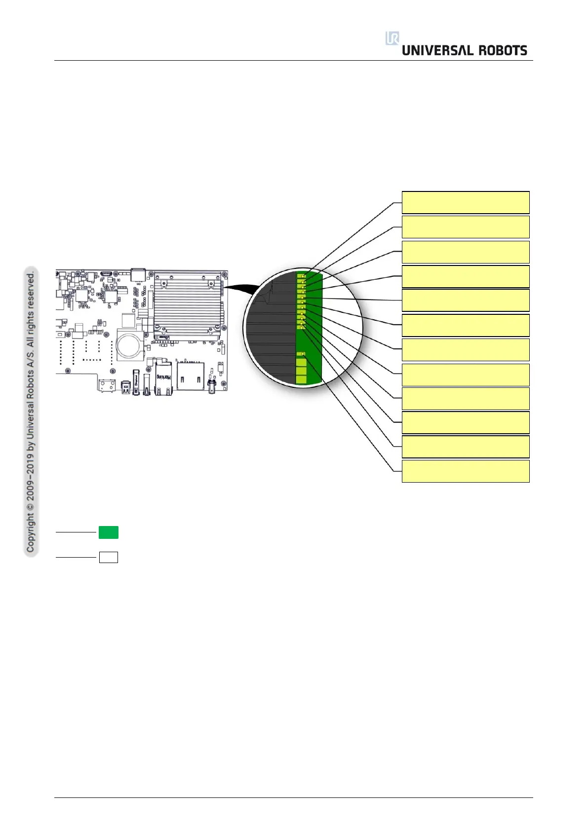
4 LED indicators
and Fuse on Safety
Control Board
6.
4.1 LED Indicators on Safety Control Board
The below LEDs
are “power”
LEDs. They are
either on
o
r off
.
LED for powe
r
Green perman
ent = Pow
er on
No color perman
ent = Error or n
o power
+24V
+12V
+12V AUX
+5V
+5V
PC
+3.3V Safety A
+3.3V Safety B
+3.3V FPGA
+3.3V PC
-4V for Analog
+1.8V/+2.5V FPGA
+48V Teach Pendant
136
138
Table of Contents
Default Chapter
3
Table of Contents
3
1 General Information
7
Purpose
7
Company Details
8
Disclaimer
8
Safety Message Types
9
2 Handling ESD-Sensitive Parts
10
3 Recommended Inspection Activities
15
Robot Arm
15
Inspection Plan
15
Visual Inspection
16
Functional Inspection
16
Cleaning
16
Control Box and Teach Pendant
17
Inspection Plan
17
Functional and Safety Inspection
18
Visual Inspection
22
Cleaning
22
4 Service and Replacement of Parts
23
Pre-Use Assessment
23
Recommended Tools
24
Robot Arm
25
Movement Without Drive Power
26
General Guidance to Separate Joint from Counterpart
27
Joint Connection Types
29
Torque Values
29
Power and Communication Connector Types on the Joint
30
Connector Location on Joints
31
Screw Connection
34
Bracket Connection
39
Tool Flange
44
Joint Verification
45
Zeroing of Joints
47
Dual Robot Calibration
53
Program Correction by Key Waypoints
53
Control Box
54
Dismantling the Control Box
54
Dismantling the OEM AC and DC Control Box
60
Assembling the Control Box Incl. OEM AC and OEM DC
68
Replacing of Teach Pendant
72
5 Software
73
Software Updates
73
Update Procedure
74
Update Timeline
78
Downgrading Vs. Restoring System Backup
79
Using Support File
80
Using Magic Files
81
Backup of Data
82
Hardware Requirements
82
Software Requirements
82
How to Access Linux Partition from Windows
82
Copy the Data from SD Card
83
6 Troubleshooting
84
Adding External Equipment for Troubleshooting Purpose
84
Support Log Reader(SLR)
85
Error Codes
86
LED Indicators and Fuse on Safety Control Board
137
LED Indicators on Safety Control Board
137
Fuse
139
Complete Rebooting Sequence
140
Protective Stop
141
7 Electrical Drawings
143
8 Spare Parts
145
Robot Arm
146
Sealing Ring Set Ur3E - 103703
147
Sealing Ring Set Ur5E - 103705
148
Sealing Ring Set Ur10E/Ur16E -103700
149
Lid Set for Ur3E - 103413
150
Lid Set for Ur5E - 103405
151
Other manuals for Universal Robots UR16e
User Manual
361 pages
Hardware Manual
103 pages
Installation Guide
40 pages
Manual
108 pages
5
Based on 1 rating
Ask a question
Give review
Questions and Answers:
Need help?
Do you have a question about the Universal Robots UR16e and is the answer not in the manual?
Ask a question
Universal Robots UR16e Specifications
General
Brand
Universal Robots
Model
UR16e
Category
Robotics
Language
English
Related product manuals
Universal Robots UR10
123 pages
Universal Robots UR10e
205 pages
Universal Robots UR5
238 pages
Universal Robots ur3
116 pages
Universal Robots UR5e
205 pages
Universal Robots UR20
47 pages
Universal Robots UR3e
361 pages
Universal Robots UR-6-85-5-A
80 pages
Universal Robots UR e Series
361 pages
Universal Robots CB3
25 pages
Universal Robots CB Series
361 pages
Universal Robots OEM Control Box
27 pages
 Loading...


