ENGLISH
42
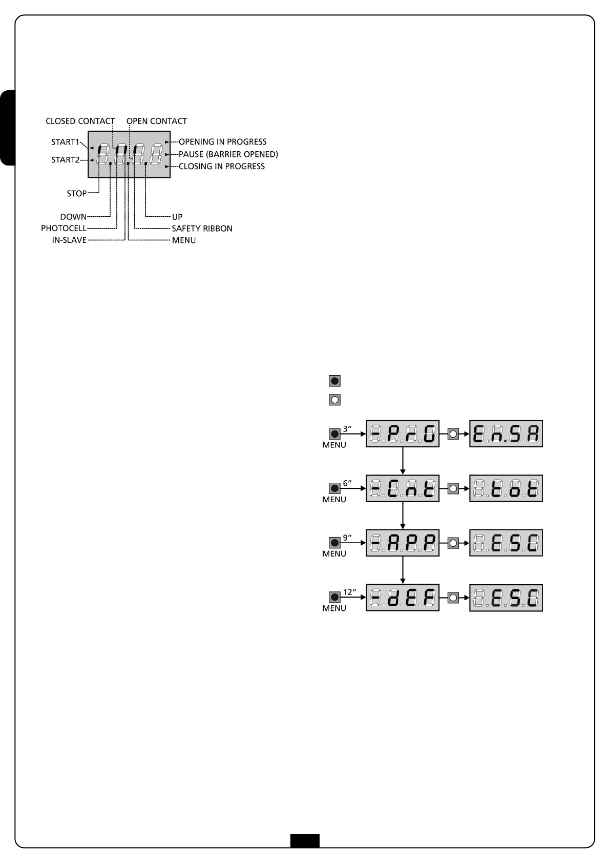
CONTROL PANEL
When power is on, the control unit checks that display correctly
operates by switching on all segments for 1.5 sec. 8.8.8.8.
F
irmware version, e.g. Pr I.0, will be viewed in the following 1.5
sec. Panel will be viewed upon completion of this test.
PLEASE NOTE: The display is off when the control unit
is in ENERGY SAVING mode.
The control panel represents the physical status of the
terminal board contacts and of the program mode keys: if the
upper vertical segment is on, the contact is closed; if the lower
vertical segment is on, the contact is open (the above picture
shows an instance where the inputs PHOTOCELL, SAFETY
RIBBONS and STOP have all been correctly connected).
The BLOCK input is connected to a micro-switch that is operated
by the inspection lock. In the case of the hatch opening, the
control unit is BLOCKED:
• Bar operation commands, from both the terminal block and
the remote controls, are not accepted
• The functions controlled by the UP, DOWN and MENU keys,
for exploring the programming menu and for operating the
bar, are permitted
• The display shows the status of the segments, alternating with
the message “SbLo”
Points being among display digits show the status of
programming push-buttons: as soon as a push-button is pressed,
its relevant point turns on.
The arrows on the left of the display show the state of the start
inputs. The arrows light when the related input is closed.
• The arrow further at the top is illuminated when the barrier is
in opening phase. If it flashes, it indicates that the opening has
been caused from the participation of an emergency device
(obstruction sensor or obstacle detector).
• The center arrow indicates that the barrier is opened in pause.
If it flashes it means that the time counter is active and
counting for the automatic closing.
• The lower arrow is illuminated when the barrier is in phase of
closing. If it flashes it indicates that the closing has been
caused by an interruption of an emergency device (obstruction
sensor or obstacle detector).
USE OF THE DOWN, MENU AND
UP KEYS FOR PROGRAMMING
Programming of the functions and times of the controller is
performed using a special configuration menu that is accessed and
explored using 3 keys, DOWN, MENU, and UP, which are located
below the display.
CAUTION: Except in the configuration menu, pressing
the UP key activates a START1 command and pressing the
DOWN key activates a START2 command.
To activate the programming modes (the display must show the
control panel), press and hold down the MENU key until -PrG
appears on the display.
Hold down the MENU key to scroll through the 4 main menus:
-PrG CONTROLLER PROGRAMMING
-Cnt COUNTERS
-APP SELF-LEARNING TIME AND FORCE
-dEF LOAD DEFAULT PARAMETERS
To enter one of the four main menus, just release the MENU key
when the menu you want appears on the display.
To move through the four main menus, press the UP and DOWN
keys to scroll through the various items. Press the MENU key to
display the current value of the selected item and change it if
needed.
key pressed
key released
 Loading...