Seismic Detectors Application Guide
Use the drill side of the GMXP0 when fixing the GMXP0 mounting plate to a concrete sur-
face.
Ensure that the correct side of the mounting plate is selected for the type of fixing to the protected sur-
face.
The drill symbol should be visible when fixing the GMXP0 mounting plate to a con-
crete surface.
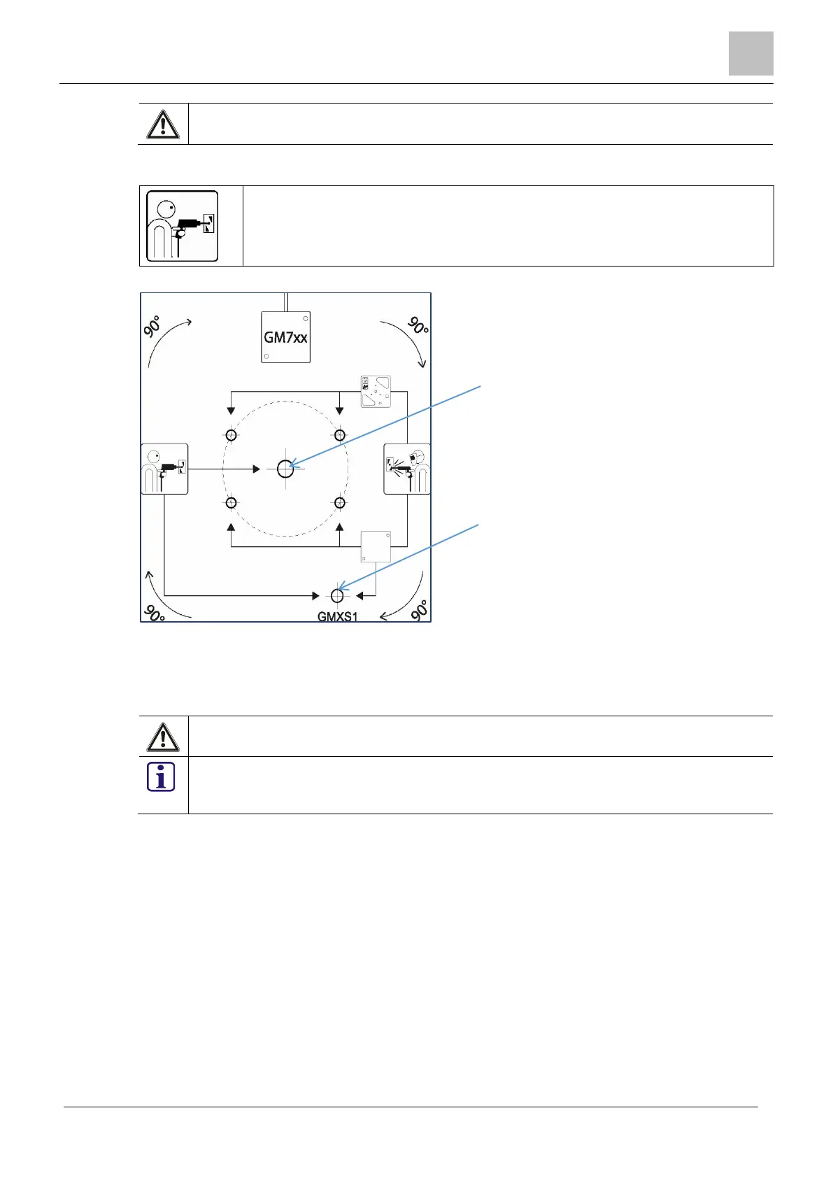
Figure 3-8: GM7xx drill template for GMXP0 on concrete
1. Drill a 10mm Ø x 60mm hole (A) and insert the steel expansion plug, supplied with the
GMXP0.
2. If the GMXS1 test transmitter is required, drill a 5mm Ø x >22mm hole (B) and insert the
GMXS1 brass expansion plug.
Do not use any other screw or expansion plug for either of these fixings.
It is essential that the GMXS1 test transmitter is secured directly to the concrete and that it
does not make contact with the GMXP0 or the detector. This is to ensure that the correct
test signal is applied to the protected surface when the GMXS1 is activated.

 Loading...
