6.6 Vault protection guidelines
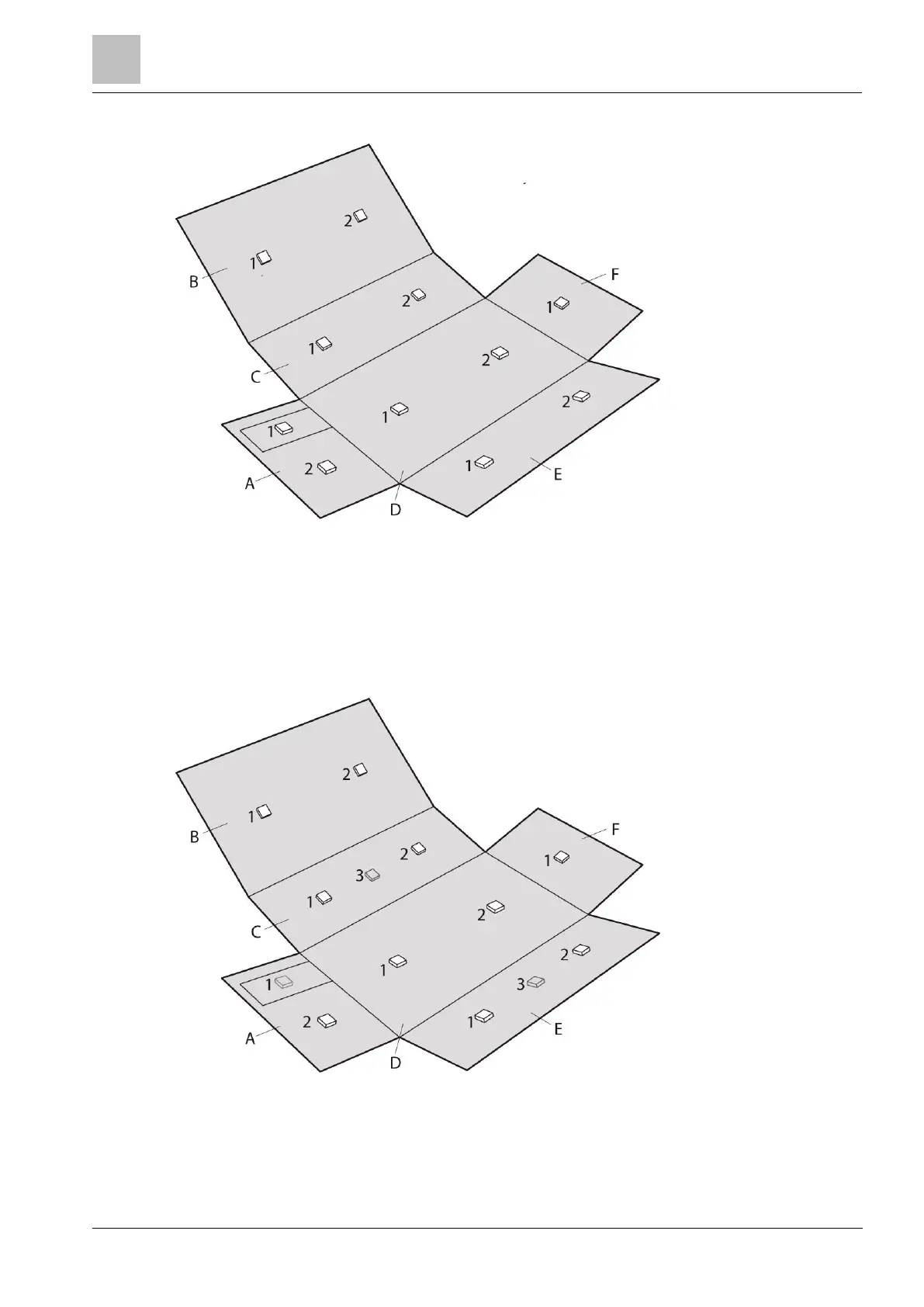
Figure 6-9: Vault protection system - example 1
Figure 6-9 shows a detection system for a vault with dimensions of 10m long, 5m wide and 2.5m
high. In this example all of the detection devices are mounted internally to the vault.
Depending upon the construction of the vault there will be a degree of detection coverage that will
transfer from the plane where the detector is installed to the adjacent plane of the vault. The joint
between two adjacent planes of the vault will normally reduce the transferred operating radius by
25%, but as the construction of the vaults and the detail of the joints between the planes can vary,
the transferred detection coverage should be ignored. Each plane should have detection coverage
as if the plane is an autonomous surface.
Figure 6-10: Vault protection system - example 2
Figure 6-10 is a similar design to the example in Figure 6-9.
Figure 6-10 shows the detectors that are mounted inside the vault in white (for example B1, B2,
A2). The test transmitters, detector, and lock protection system that are mounted externally to the
vault are shown in grey (for example A1, E3).

 Loading...
