EasyManuals Logo
Home>Vanderbilt>Security Sensors>GM7 Series

Vanderbilt GM7 Series User Manual

Vanderbilt GM7 Series
66 pages
To Next Page IconTo Next Page
To Previous Page IconTo Previous Page
Page #53 background imageLoading...
Page #53 background image
Interface to SPC Panel/System
9
53
Vanderbilt
Seismic Detectors Application Guide
I-200153-1
08.2016
9 Interface to SPC Panel/System
9.1 General Electrical Connections
There are a number of different connection options for the monitoring of the seismic detectors
available from the SPC system. Vanderbilt recommend that the dual end of line options are se-
lected, as they provide the most comprehensive coverage and reporting.
Optimum performance of the combined SPC/GM7xx system requires selection of the financial
package in SPC. See Section 9.2 for more information on the additional benefits.
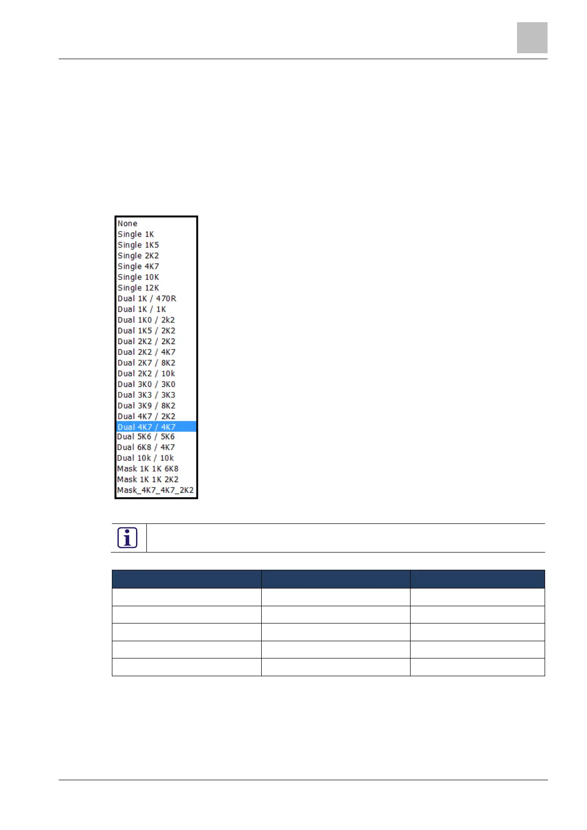
The list of available end of line monitoring is as follows and the default value is Dual 4K7/4K7 end
of line resistor:
Figure 9-1: End of line monitoring options
Note that resistors are not supplied with GM7xx seismic detectors.
A quick comparison of the benefits between single and dual end of line monitoring follows:
Status
Dual end of line 4K7
Single end of line 4K7
Normal
4K7
4K7
Tamper
Infinity
Infinity
Alarm
9K4
Infinity
Short circuit
0 ohm
0 ohm
Open circuit
Infinity
Infinity
Table 9-1: End of line monitoring
Note: the SPC panel detects the different resistance values and reports the condition to the user of
the SPC system as detailed in the status column.
The electrical connection for seismic detectors (GM710, GM730, GM760, GM775) is detailed in
Figure 9-2.

Table of Contents

Questions and Answers:

Question and Answer IconNeed help?

Do you have a question about the Vanderbilt GM7 Series and is the answer not in the manual?

Vanderbilt GM7 Series Specifications

General IconGeneral
BrandVanderbilt
ModelGM7 Series
CategorySecurity Sensors
LanguageEnglish

Related product manuals