Seismic Detectors Application Guide
6 Design
Planning the detection layout requires the consideration of many factors in order to provide the
highest security level.
The type of detector.
The operating radius of the detector.
The spacing of the detectors.
The detector accessories that will complement the design and assist with the detection
properties of the detectors. For more information on detector accessories, see Chapter 4
Installation - Accessories.
6.1 General Principles
Always consider the spacing of detectors along with the operating radius to determine the correct
number of detectors required to provide comprehensive detection coverage for the application. The
coverage area is the maximum area monitored by a single detector. A detector’s coverage area
depends on the material type the detector is mounted on, in conjunction with the setting of the op-
erating radius.
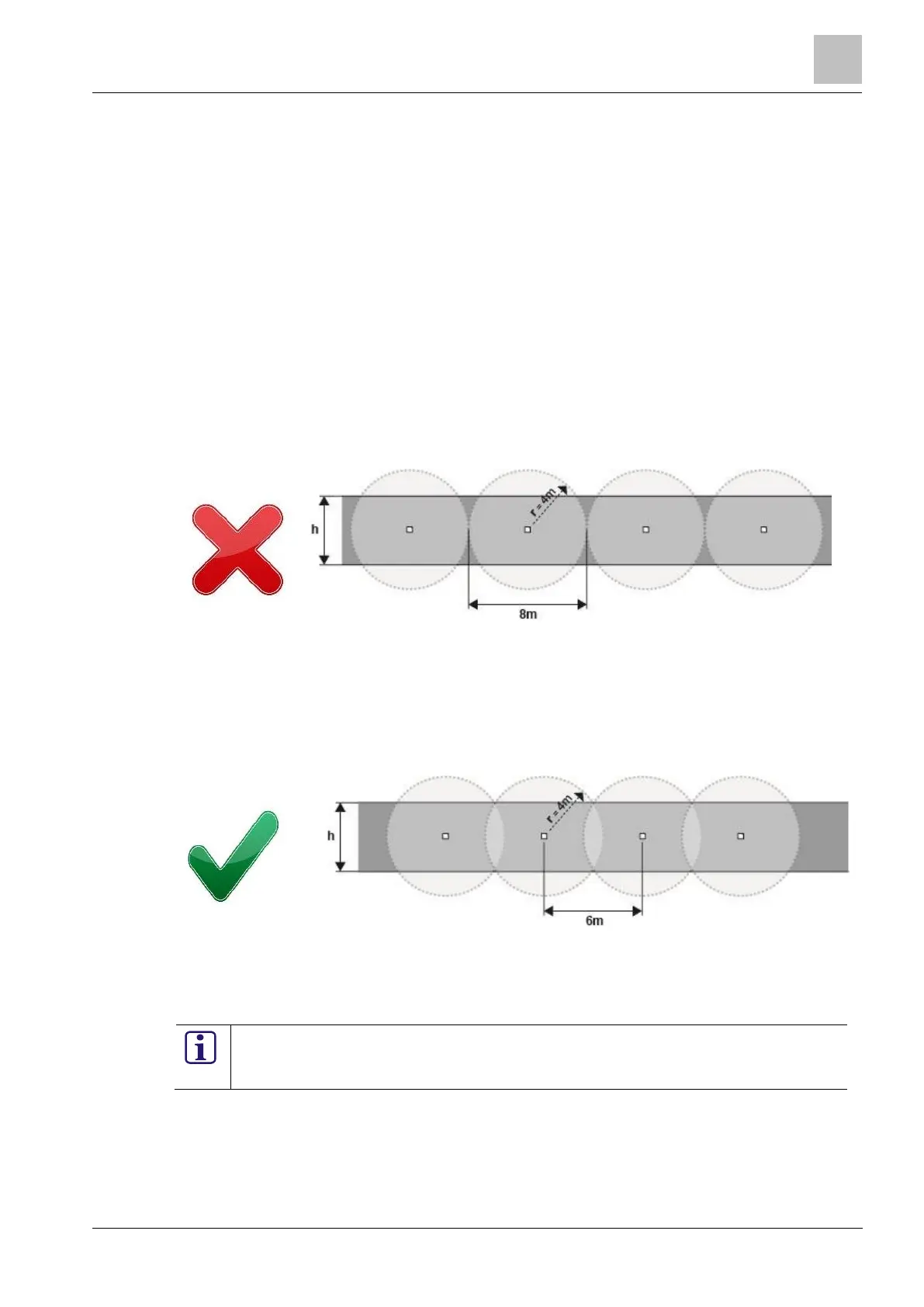
Figure 6-1: Insufficient seismic detector coverage
Figure 6-1 shows an example of the coverage area for a seismic detector with an operating radius
(r) of 4m on a wall height (h) of 5m. As the coverage area of the detectors do not overlap, there are
parts of the protected surface (the darker areas in Figure 6-1) where detector coverage is insuffi-
cient for optimum system performance. It is essential that the detectors are not installed as shown
in Figure 6-1 as the system performance will be undermined.
Figure 6-2: Revised seismic detector spacing
Figure 6-2 shows the spacing of the seismic detectors that is required in order to provide adequate
coverage for the protected surface.
The coverage area of seismic detectors should always overlap to provide 100% detec-
tion coverage. To ensure complete detection coverage the maximum spacing distance
(sd) for the seismic detectors must be determined.
The installer requires the following information for each wall of the protected area:
Optimum seismic detector spacing and location
Optimum number of seismic detectors

 Loading...
