EasyManuals Logo
Home>Vector>Controller>TRA-F12 A Series

Vector TRA-F12 A Series User Manual

Vector TRA-F12 A Series
34 pages
To Next Page IconTo Next Page
To Previous Page IconTo Previous Page
Page #5 background imageLoading...
Page #5 background image
TRA-F12x-A
TECHNICAL SPECIFICATIONS
Doc: 70-00-0792B V1.3, 20220830 © Vector Controls GmbH, Switzerland Page 5-34
Subject to change without notice www.vectorcontrols.com
VECTOR
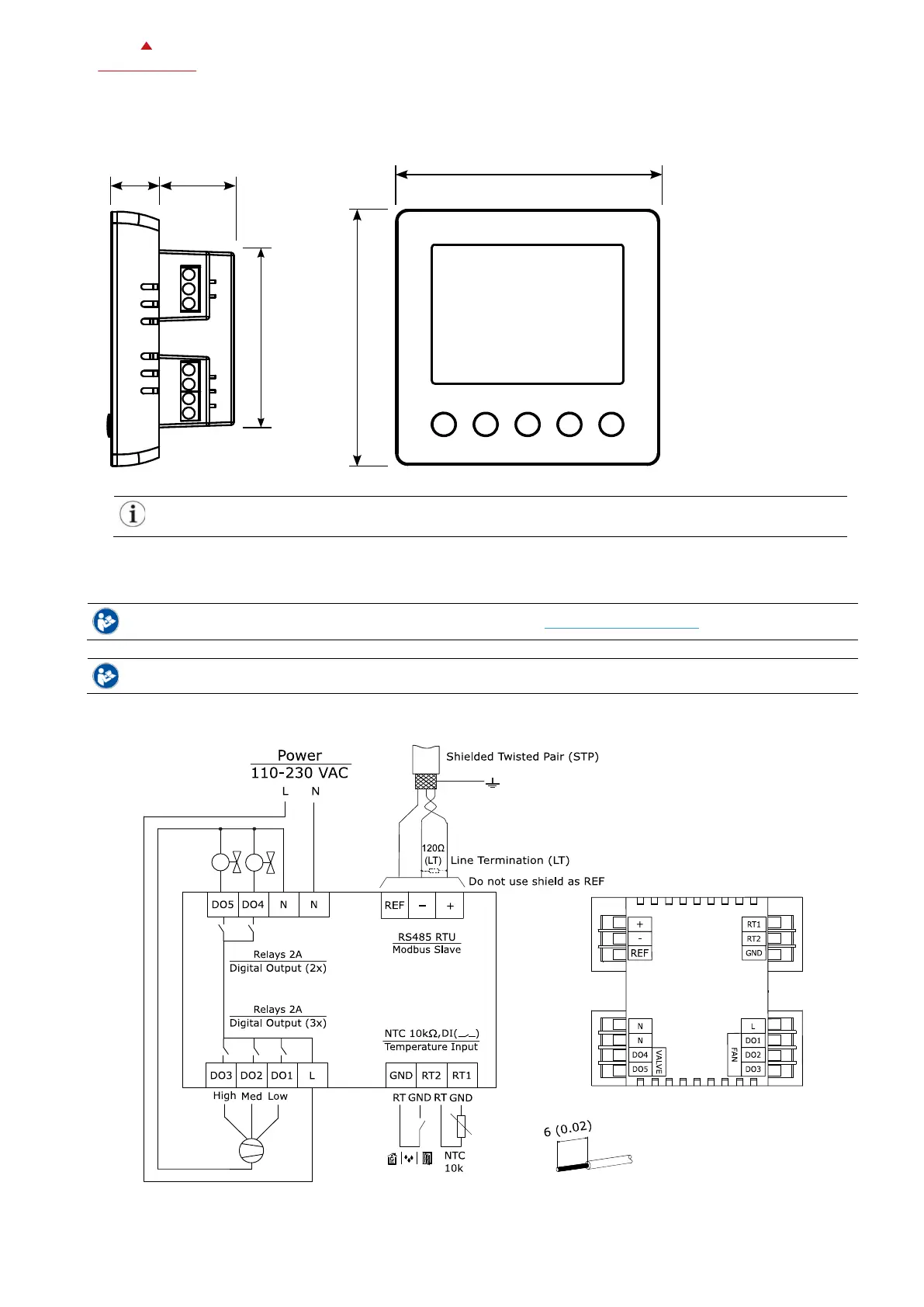
2.2 Dimensions, mm (inch)
For flush mounting, a 75 x 75 x 35 mm (3.0 x 3.0 x 1,4 inch) installation box or larger must be used.
See Ordering for recommended installation boxes (chapter 1.3, page 3).
2.3 Connection diagram
For details see the TRA-F12x-A installation sheet no. 70-000791 (www.vectorcontrols.com).
The wiring for the different predefined TRA-F12x-A applications can be found in chapter 5.6.3, page 19.
A typical connection of the TRA-F12x-A is shown below:
61(2.4)
16(0.6) 25(1.0)
88(3.5)
88(3.5)

Table of Contents

Questions and Answers:

Question and Answer IconNeed help?

Do you have a question about the Vector TRA-F12 A Series and is the answer not in the manual?

Vector TRA-F12 A Series Specifications

General IconGeneral
BrandVector
ModelTRA-F12 A Series
CategoryController
LanguageEnglish

Related product manuals