EMR3 Truck Installation Installing the Temperature Probe (Optional)
34
.
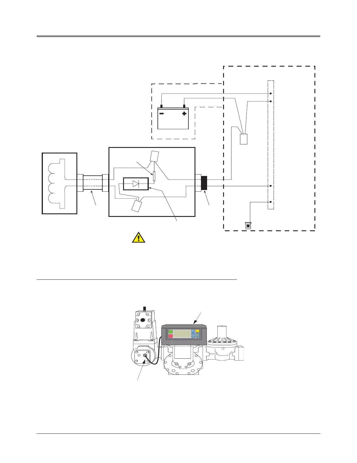
Figure 25. Connecting 3-way valve to the IB box
Installing the Temperature Probe (Optional)
1. Locate the thermowell in the metering system (see Figure 26).
Figure 26. Example thermowell installation
V+
Ground
DH1
RELAY 1
Power side
terminals
Wire Nut
Wire nut
Wire nut
3-Way Valve Solenoid
IB Box
Cord Grip
Vehicle power
NO
COM
emr\3waywir.eps
Nipple
J-Box
Ground
Clamp
White sleeve
(on lead)
Suppressor diode
V/R Kit P/N 846000-022
CAUTION! use of the suppressor diode
is only approved for vehicle applications.
se this port for Optional
Display Head
emr\therm3.eps
START
FINISH
MODE PRESET
NEXT
ENTER
VOLUME CURRENCY RATE SETUP
 Loading...