EMR3 Terminal - Fueling Depot Installation C&C Mode Switch Options
44
7. Replace the Display Head cover and screw in the four cover retaining bolts just enough to hold them in (the
cover will be removed later for system calibration).
C&C Mode Switch Options
There are three C&C mode switch configurations:
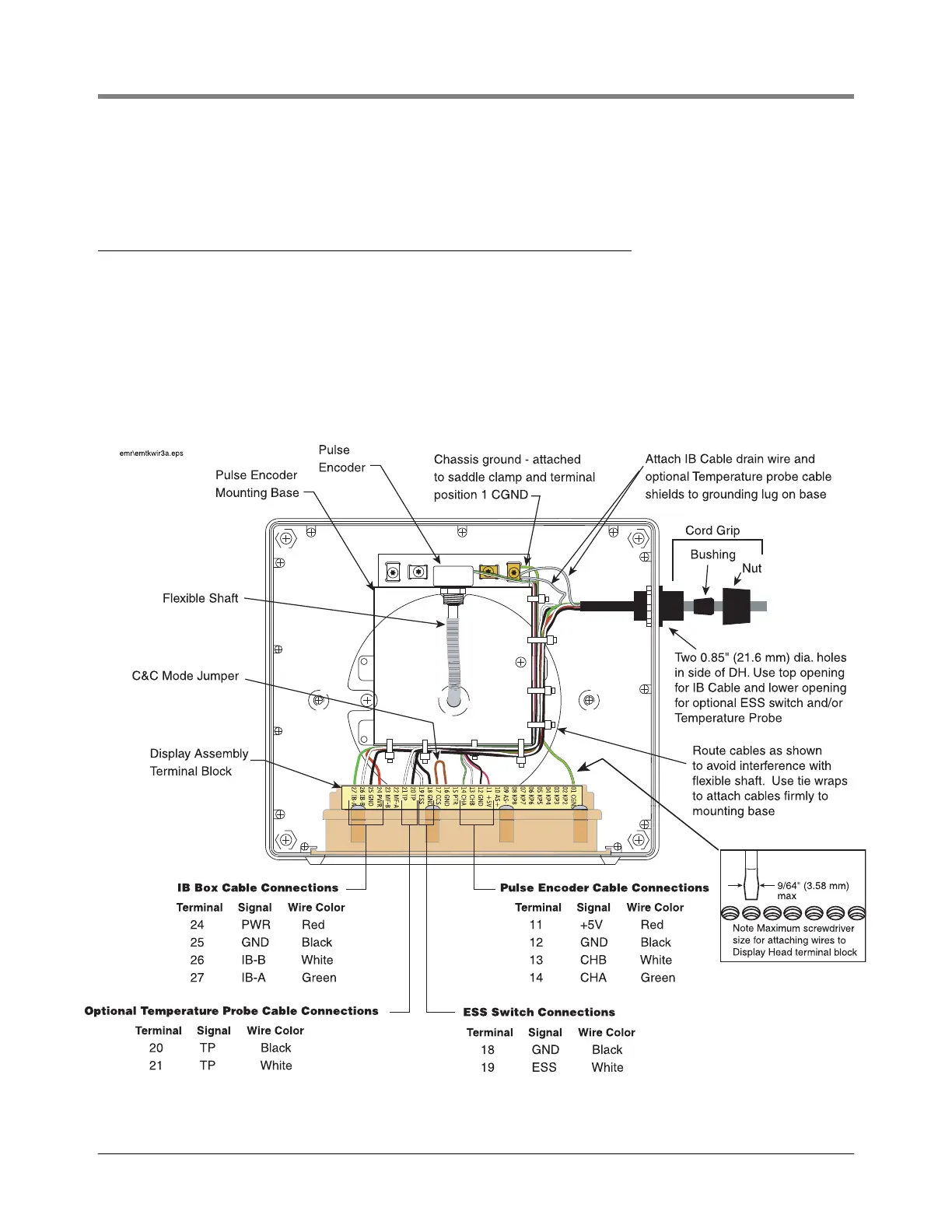
1. A C&C wire jumper (see Figure 34) - standard configuration. To enter C&C mode, you remove one end of the
jumper from its terminal, and you reconnect it when finished.
2. An optional front panel C&C switch is available for the Remote Display Head (ref. Figure 30 on page 39).
3. An optional C&C corner switch assembly which fits into a corner of the Display Head’s housing (P/N 846000-
018). To enter C&C mode, you remove the corner bolt of the Display Head’s cover that presses against the
switch actuator lever, and you replace the bolt when finished (see Figure 35)
Figure 34. Display head cable wiring and switch locations
 Loading...