1
Introduction
General
This manual covers truck and terminal - fueling depot installation of the Veeder-Root Electronic Meter Register
(EMR
3
) System. The EMR
3
System consists of several major components:
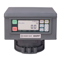
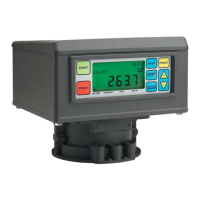
• Display Head (DH) - The Display Head replaces the mechanical register on a truck or a terminal - fueling
depot fuel flow meter. Using the Display Head front panel display and the keys on its face, the operator can
choose to dispense either a preset or a variable quantity of product. An optional Temperature Probe is available
for temperature compensated product deliveries.
The Display Head must be configured and calibrated before it is placed in service. Once the initial Configuration
and Calibration procedures are complete, the Display Head is sealed for weights and measures certification.
• Interconnection Box (IB) - The IB box that contains the EMR
3
System control circuitry. The IB is mounted in
the truck cab or the terminal - fueling depot office. The IB provides an intrinsically-safe barrier for connections to
one or two Display Heads located at dispensing points in the hazardous area. IB boxes can accept either 12 or
24 Vdc input power. Note: check label affixed to outside of IB box to verify input power ratings.
• Printer (optional) - A multi-part slip printer (truck cab) or roll printer (terminal - fueling depot office)
• Remote Display (Optional) - For use as a slave Display unit in the cab along with a meter mounted Display
Head, or for use as a Display Head (w/ Remote Pulser) in dual meter configurations. Required when used with a
meter mounted Remote Pulser.
• Remote Pulser (Optional) - Mounts directly onto meter with cable to Remote Display (required). This pulser is
functionally identical to the internal encoder.
System Specifications
• System power: 12 or 24 Vdc, ±20%, fused @ 5 A
• Pulser Capacity: 0 - 1000 Hz
• Temperature compensation range: -45 to +158°F (-50 to +70°C)
• Communication between Display Head and IB: RS-485; 2-wire half duplex; custom protocol; 19,200
baud; 8 bit; no parity; 1 stop bit
• Communication between Printer and IB: RS-232; 9600 baud; 8 bit; no parity; 1 stop bit
• Display Head and IB Operating temperature range: -13 to +158°F (-25 to +70°C)
• Display Head and IB Storage temperature range: -40 to +185°F (-40 to +85°C)
• Printer power: +24 Vdc, 2 A (supplied by the IB)
• Printer Operating temperature range: +32 to +122°F (0 to +50°C)
• Printer Storage temperature range: +32 to +122°F (0 to +50°C)
• Weights and Measures: Designed to meet NIST, OIML, and Canadian W&M specifications
• Relay Ratings: 5A at 120 Vac, 2.5A at 240Vac, 24 Vdc
 Loading...