EMR3 Terminal - Fueling Depot Installation Pulse Output for EMR3
53
SP1 and SP2
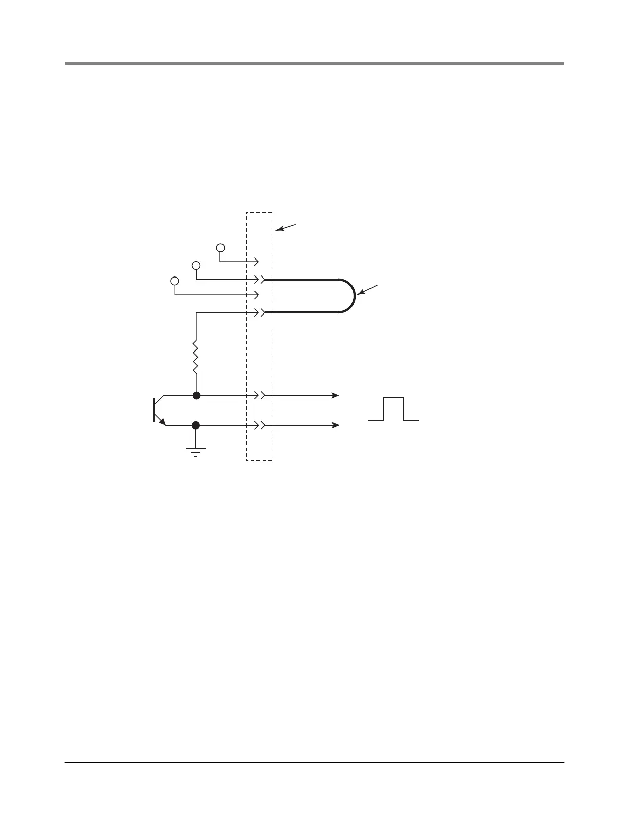
• SP1 and SP2 are open collector outputs with an internal pull-up resistor (2.2K) tied to Input V. The output
voltage can be set to either 5, 12, or 24 volts depending on the location of the pulse voltage selector jumper
wire (see Figure 40).
• A low or 0 volt signal which indicates that the corresponding Display Head is in the delivery state
Figure 40. POUT-1 output diagram (12V pulse output voltage selected in this example)
WIRE SIZE AND/OR DISTANCE LIMITATIONS
POUT-1, POUT-2, SP1, and SP2
• Wire size 16 - 24 AWG,
• 5V out length 250 ft. (76.2 m)
• 12V out length 500 ft. (152.4 m)
• 24V out length 1000 ft. (304.8 m)
12V
5V
24V
Input V
12V
IB Terminal Block
To External
Pulse Counter
IB Circuit Board
Pulse Output Voltage
Select Jumper
POUT-1
(-)
(+)
Ground
emr\pulsoutdia.eps
0
12V
 Loading...