9
ART.3980: MOUNTING PLATE AND PCB
CONNECTIONS FOR 3000 SERIES
MOUNTING PLATE INSTALLATION AND
PCB CONNECTIONS
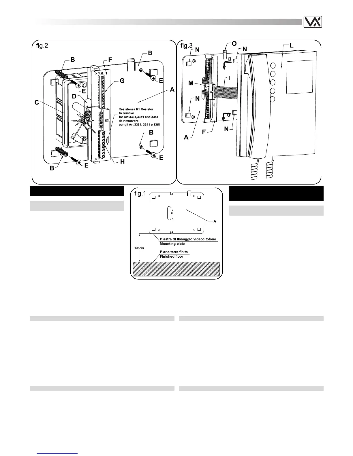
- Place the mounting plate A against the wall as
shown in fig.1 (135cm from floor level); and
mark the fixing holes for the four wall plugs B
(fig.2) and for the back box C if used (fig.2)
which must be flushed into the wall in line with
the opening D as shown in fig.2.
- Once the back box
(1)
C (if used) is flushed
into the wall, drill the four fixing holes and
insert the wall plugs B. Thread the cables
through the opening D and fix the mounting
plate A to the wall with the 4 screws E (fig.2),
using a Philips screwdriver.
- Fit the PCB F against the mounting plate A
ART.3980: PIASTRA DI FISSAGGIO E
SCHEDA DI CONNESSIONE PER LA SERIE
3000
INSTALLAZIONE PIASTRA E SCHEDA DI
CONNESSIONE
- Appoggiare al muro la piastra di fissaggio A
come indicato in fig.1 (135cm da terra);
prendere i riferimenti (fig.2) dei quattro fori per
l’inserimento dei tasselli ad espansione B e
quello per la scatola da incasso C che, se
impiegata, dovrà essere murata in posizione
centrale rispetto all’apertura D, al fine di
agevolare il passaggio dei fili come mostrato
in fig.2.
- Murare la scatola da incasso
(1)
C, eseguire i 4
fori ed inserire i tasselli ad espansione B.
Passare i cavi nell’apertura D e fissare la
piastra A con le 4 viti E (fig.2)
as shown in fig.2; insert the wires
(2)
(As short as possible) into terminals
G-H. Secure them using a terminal screwdriver.
- Unclip the PCB F (fig.2), rotate it 90º anticlockwise and fit it into its
housing as shown in fig.3.
INSTALLING THE VIDEOPHONE ONTO MOUNTING PLATE
- As shown in fig.3, move the videophone L close to the mounting plate A
so that the ribbon cable will reach the connector I.
- As shown in fig.3, connect the female plug on the ribbon cable I coming
from the videophone to the male plug connector M on the PCB F.
- Place the videophone L against the 4 hooks N on the mounting plate A
and push down: the videophone will automatically lock into place using
clasp O as shown in fig.3.
- To remove the videophone from the wall, push the clasp O in the
direction of the wall with a screwdriver and at the same time push the
videophone upwards.
NOTES
1
We recommend using a back box (not provided) in order to contain
excess wire behind the back plate.
2
The wires must be connected to the terminals as shown on the relevant
wiring diagrams. For signal descriptions please refer to table 3 (on page
8) for Art.3311,3411 and 3511 (coax videophones) and to table 4 (on
page 8) for Art.3331, 3431 and 3531 (non coax videophones).
utilizzando un cacciavite a croce.
- Appoggiare la scheda di connessione F sulla piastra A come mostrato
in fig.2; inserire
(2)
i fili (che devono essere più corti possibile) nelle
morsettiere G ed H e serrare con un cacciavite a taglio.
- Fissati i fili, sfilare la scheda di connessione F (fig.2), ruotarla di 90º in
senso antiorario ed infilarla nella propria sede come mostrato i n fig.3.
APPLICAZIONE DEL VIDEOCITOFONO
- Avvicinare il videocitofono L alla piastra A come da fig.3, per agevolare
la connessione del flat I.
- Come mostrato in fig.3, inserire il connettore del flat I, che fuoriesce
dalla parte posteriore del videocitofono, nel connettore M della scheda di
connessione F.
- Facendo corrispondere le 4 fessure presenti sulla base del videocitofono
L con i 4 incastri N della piastra A, appoggiare il video sulla piastra e
spingerlo verso il basso fino allo scatto, compiendo un movimento come
mostrato dalle frecce in fig.3.
- Per rimuovere il videocitofono, spingere con un cacciavite a taglio il
dente O verso il muro e, contemporaneamente, spingere il videocitofono
verso l’alto.
NOTE
1
Si consiglia di utilizzare una scatola da incasso (non in dotazione) al fine
di contenere l’eventuale lunghezza eccedente dei fili.
2
Eseguire i collegamenti alla morsettiera rispettando gli schemi forniti a
corredo del videocitofono (per applicazioni differenti da quelle degli
schemi standard, rivolgersi al proprio rivenditore). Per le descrizioni dei
segnali, fare riferimento alla tabella 3 (pag.8) per gli Art.3311, 3411 e
3511 (videocitofoni con coassiale) e alla tabella 4 (pag. 8) per gli
Art.3331, 3431 e 3531 (videocitofoni per sistema 4+1).
 Loading...