68
VIDEOINTERCOM SYSTEM WITH “N”
USERS AND THREE OR MORE
AUTOMATICALLY SWITCHED OUTDOOR
STATIONS
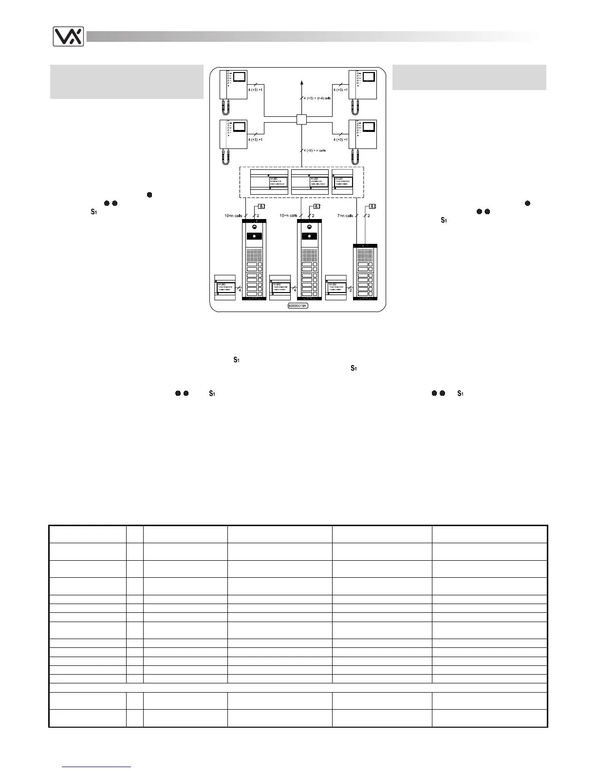
This type of installation is used in a building
with three entrances or more: in this case we
have 2 entrances with a push button panel
and one camera module and 1 entrance with
only the speaker unit. The Art.892 switching
relay allows automatic switching of video
signal, speech line and other services to the
outdoor station from where the call has been
placed. If the dashed connections shown on
the wiring diagram are made, in this system
the camera recall will be possible on all
entrances by pressing the
button for the
entrance A, the
button for the entrance B
and the
button for the entrance C.
Naturally the recall on the entrance “C”
enables only the speech.
Installing the system
a. Consult the table below to obtain the
necessary items required.
b. Run the correct size cables (see page
26).
c. Test installation (see page 29).
IMPIANTO VIDEOCITOFONICO PER “N”
UTENTI CON 3 O PIÙ INGRESSI
COMMUTATI IN AUTOMATICO
Questo genere di installazione può essere
impiegato per edifici o complessi abitativi con
3 o più ingressi indipendenti; nell’esempio
mostrato ci sono 2 ingressi video ed 1 audio.
Lo scambiatore di ingressi Art.892 (o Art.502N
per i posti esterni audio) consente di
commutare automaticamente il segnale video,
l’audio e gli altri servizi, verso il posto esterno
dal quale è stata eseguita l’ultima chiamata.
Realizzando le connessioni tratteggiate
mostrate nello schema, da qualsiasi
videocitofono dell’impianto sarà possibile
eseguire l’auto-accensione sull’ingresso
desiderato: premere il pulsante
per
l’ingresso A, il pulsante
per l’ingresso B
ed il pulsante
per l’ingresso C. Ovviamente
l’autoaccensione sull’ingresso “C” abilita
solamente la fonia.
Realizzazione dell’impianto
a. Consultare la tabella di fondo pagina per
il materiale occorrente;
b. Posare il cavo rispettando le sezioni dei
fili (vedi pag.26);
c. Collaudare l’impianto (vedi pag.29).
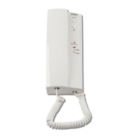
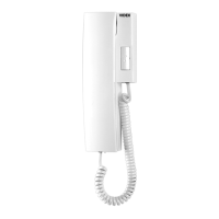
Extra services and accessories
It is possible to install on the system additional accessories or/and have
extra services by using service push buttons:
1. installing an additional speaker (see page 34 fig.9).
2. installing an Intercom in parallel with videophone (see page 33 fig.6).
3. executing an extra service by using service button :
- stairway light or other service (see page 33 fig.5).
Servizi ausiliari ed accessori
È possibile installare nell’impianto degli accessori aggiuntivi e/o usufruire
di servizi ausiliari, utilizzando i pulsanti di servizio:
1. installazione di una suoneria supplementare (vedi pag.34 fig.9);
2. collegamento di un citofono in parallelo ad un videocitofono (vedi
pag.33 fig.6);
3. pulsante
disponibile per i seguenti servizi:
- accensione luci scale o altri servizi (vedi pag.33 fig.5).
NOTES
- To use the service push buttons
and as recall push buttons
move JP1 and JP2 to B position.
- To add more entrances, add for each one the necessary components
for the outdoor station and one Art.892 (or 502N for audio
entrances): for each additional entrance repeat the connections as
shown on the wiring diagram.
NOTE
- Per utilizzare i pulsanti di servizio
e come pulsanti di “auto-
accensione”, spostare i jumper JP1 e JP2 in posizione B.
- Per ciascun ulteriore ingresso da collegare, oltre ai componenti
necessari per il posto esterno, aggiungere un Art.892 per gli ingressi
video o un Art.502N per quelli audio e ripetere le connessioni
eseguite per gli altri ingressi.
Art.
Qty
Qta
Description Notes Descrizione Note
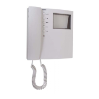
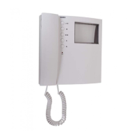
3331 or
3431
n
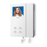
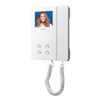
Videophone
n = Videophones in the
system
Videocitofono n = Videocitofoni nel sistema
316 n/4
Video Distributor
one can supply video
signal up to 4 videophones
Distributore video
1 può fornire il segnale video a 4
videocitofoni
3980 n
Mounting plate and pcb
connections
one for each videophone
Piastra di fissaggio e scheda
di connessione
una per ogni videocitofono
522 1
Power Transformer
Trasf. di alimentazione
835M-2 1
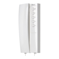
Speaker Unit
Portiere elettrico
850 2
Power Transformer
Trasf. di alimentazione
831M-0-1-2 or
831M-0-1-2colour
2
Camera Unit
Unità di ripresa
892 2
Entrances switch for video entrances
Scambiatore di ingressi per ingressi video
502N 1
Entrances switch for audio entrances
Scambiatore di ingressi per ingressi audio
834N x
Five diode pcb module one for each extension panel
Modulo con 5 diodi uno per ogni modulo pulsantiera
843-4-5 x
Ext. front panel module as may be required
Moduli pulsantiera quantità in base alle esigenze
852-3 x
Front Support as may be required
Sostegno porta moduli quantità in base alle esigenze
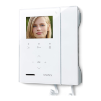
To use videophones with memory board
Per utilizzare videocitofoni con memoria video
3531 n
Videophone with
memory board
Videocitofono con memoria
video
521B n/4
Additional power supply
For memory board power
supply
Alimentatore addizionale Per alimentazione memoria video
 Loading...