 Loading...


Do you have a question about the Viessmann Vitorond 100 and is the answer not in the manual?
Ensures installation, adjustment, service, and maintenance are performed by qualified professionals.
Emphasizes reading and storing all applicable documentation for reference by service personnel.
Instructs contractors to familiarize owners with equipment operation and safety precautions.
Warns about chemicals in air causing poisonous by-products and equipment damage.
Highlights risks of CO poisoning from improper installation, adjustment, or maintenance.
Stresses the need for adequate fresh air for safe operation and combustion.
Warns against operating without a venting system to prevent CO poisoning.
States that failure to follow documentation renders the warranty null and void.
Addresses potential cancer hazard and irritation from airborne fibers, requiring special care.
Lists toxic substances in materials and combustion, requiring safety precautions.
Details adherence to local, national, and industry codes for installation and wiring.
Specifies compliance with requirements for the mechanical room where the boiler is installed.
Outlines safety procedures like deactivating power and closing oil supply before servicing.
Directs users to applicable literature and advises leaving it at the installation site.
Explains symbols, flag words (WARNING, CAUTION, IMPORTANT), and their meanings.
Details air supply calculations for boilers located in unconfined spaces.
Specifies air supply methods and openings for boilers in confined spaces.
Explains how louvers and grilles affect free area calculations for air openings.
Provides guidance on installing combustion air openings and required duct diameters.
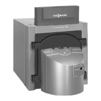
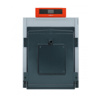
Lists items to check for delivery, including boiler casting, jacket, and burner.
Provides detailed steps for safely unpacking and maneuvering the boiler from its crate.
Specifies required clearances from the boiler and burner to combustible materials.
Details recommended clearances for cleaning and servicing the boiler.
Guides on positioning the boiler, including incline for leveling and proximity to the chimney.
Provides step-by-step instructions for installing insulation blankets and panels on the boiler.
Describes the stainless steel combustion chamber insert and its dimensions.
Covers codes and general requirements for safe venting of combustion products.
Details piping connections for water supply, return, and safety devices with Aquastat control.
Instructions for installing the pressure relief valve and boiler control with Aquastat.
Details piping connections for water supply, return, and safety devices with Vitotronic control.
Instructions for installing the pressure relief valve and boiler return injector with Vitotronic.
Outlines procedures for hydrostatically testing the boiler for leaks.
Overview of installing the Beckett oil burner, including fuel and nozzle specifications.
Provides details on fuel type, oil nozzle, and burner calibration for Beckett burners.
Step-by-step guide for mounting the Beckett burner, including air tube insertion.
Instructions for connecting the oil piping to the Beckett burner, following safety codes.
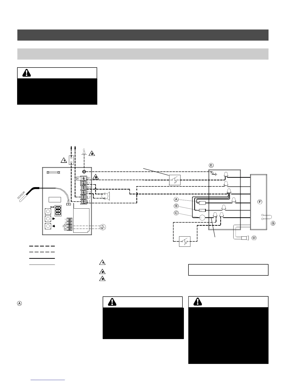
Details wiring connections for the Beckett burner with Aquastat control and room thermostat.
Presents wiring diagrams for Beckett burners with Aquastat and specific control modules.
Explains wiring connections for the Beckett burner with Vitotronic control.
Guides on installing the Vitotronic control console and connecting sensors.
Instructions on how to install the boiler coding card for proper system configuration.
Details the installation and connection of the pump junction box for Vitotronic systems.
Illustrates the burner wiring harness and its connection points.
Provides wiring diagrams for Beckett burners connected to Vitotronic controls.
Shows wiring for Beckett burner with Genisys and Vitotronic controls, including outdoor reset.
Overview of installing the Riello oil burner, including fuel and nozzle specifications.
Provides details on fuel type, oil nozzle, and burner calibration for Riello burners.
Step-by-step guide for mounting the Riello burner.
Instructions for connecting the oil piping to the Riello burner, following safety codes.
Details wiring connections for the Riello burner with Aquastat control and room thermostat.
Explains connecting the Riello burner wiring harness to the Honeywell high limit and sub-base.
Presents wiring diagrams for Riello burners with Aquastat control and outdoor reset module.
Guides on installing the Vitotronic control console for Riello burners.
Explains wiring connections for the Riello burner with Vitotronic control.
Details the installation and connection of the pump junction box for Vitotronic systems with Riello.
Illustrates the Riello burner wiring harness and its connection points.
Provides wiring diagrams for Riello burners connected to Vitotronic controls.
Instructions on how to install the boiler coding card for Riello burner configuration.
Explains the importance of combustion analysis for verifying settings and local conditions.
Provides technical data and settings for calibrating Beckett burners on different boiler models.
Provides technical data and settings for calibrating Riello burners on different boiler models.
Details the function and adjustment of the barometric draft regulator during burner operation.
Lists the steps involved in performing maintenance and service on the boiler.
Lists essential tools and supplies required for boiler maintenance and service.
Detailed instructions for shutting down, opening, cleaning, checking, and calibrating the boiler.
Catalog of replacement parts for the Vitorond 100 boiler, including part numbers and diagrams.
A log for recording periodic service and maintenance performed on the boiler.