Connections
40
Burner Set-up (Beckett control) (continued)
Pump junction box (with Vitotronic control)
The pump junction box supplies power
to field supplied pumps. It is shipped
with the boiler and must be installed
whenever each of the boilers is installed
in conjunction with the following
controls:
- Vitotronic 100, KK10
- Vitotronic 100, KW10
If installing Vitotronic 200, Vitotronic
100- KW10A / KW10B, discard the
pump junction box.
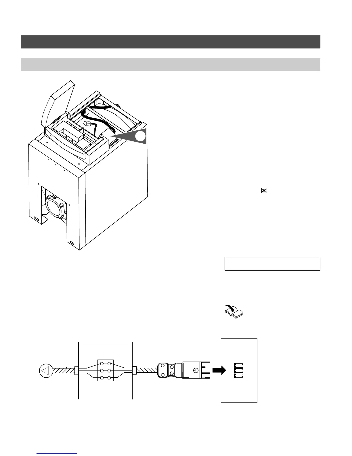
1. Pump junction box must be placed
underneath top panel near the back
of the boiler. See Fig. 37.
2. Connect the
RAST-5 plug-in
connector of the Pump Junction Box
to the main circuit board of the
control. See Fig. 38.
3. Feed the power supply cabling of the
system pump through the opening at
the back of the boiler and connect to
terminals in pump junction box. See
Fig. 38.
Run BX
(armoured cable) or any other
approved wire (required by local authority
having jurisdiction) from junction box
terminal to heating circuit pump.
Installation Instructions
Vitotronic 100
5671 044 v1.0
Fig. 37
Installation location of pump junction box
1.
Fig. 38
Pump junction
GRN
WHT
BLK
20
20
N
L
Pump
Pump junction box
Space heating pump
120 VAC, 3 amps
maximum
Vitotronic control
Models KK10, KW10
Refer to corresponding
Vitotronic control manual
IMPORTANT
 Loading...