D-303973 PowerMaxExpress Installer's Guide 17
second alarm will be considered as a confirmed alarm
(for confirmed alarm reporting, (see par. 4.5.3).
Options: disable 30 min., 45 min., 60 min., or 90 min.
4.4.34 AC FAIL REP
(Fig. 4.4, location 34). Here you determine the time
interval between AC power failure occurrence and the
failure reporting. Options: 5 minutes, 30 minutes, 60
minutes or 180 minutes.
Note: To comply with EN requirements, set to 60 min.
max.
4.4.36 User Permission
(Fig. 4.4, location 36). Here you determine whether the
access to the INSTALLER MODE requires user permission.
If you select ENABLE, the installer mode will be accessible
only through the user menu after entering the user code.
Options: Enable, Disable.
Note: This menu is not available when partition is enabled.
Note: To comply with EN requirements, "Enable" must be
selected.
4.4.39 Key Zones Options (Optional)
(Fig. 4.4, location 39). Here you determine whether or not
the system can be armed and disarmed by zones 21-28, 29
or 21-29, provided that for these zones "non-alarm type"
and "z-key enable" was predefined (see par. 4.3 and
APPENDIX E14).
Key zones can be wireless or wired zones.
When using wireless key zones, you can install and use
the following transmitters:
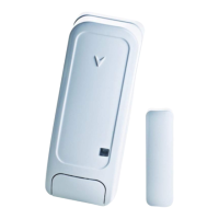
MCT-100
MCT-102
MCT-302
MCT-320
The right pushbutton on the MCT-102 transmitter or input
2 of the MCT-100 transmitter is used for arming in AWAY
mode. The left pushbutton on the MCT-102 transmitter or
input 1 of the MCT-100 transmitter is used for disarming.
When using wired key zones an open circuit arms the
alarm system in AWAY mode and a closed circuit changes
the state of the alarm system from AWAY mode to Disarm.
(For information on how to connect to wired key zones,
see Fig. 3.1C Zones and Sirens Wiring.)
IMPORTANT! Enrolment of the MCT-100 or MCT-102
transmitter must be performed via the right pushbutton on
the MCT-102 transmitter or input 2 of the MCT-100
transmitter (see section 4.3).
Note: Key Zones do not comply with Belgium TO14A and
EN 50131-5-3.
Caution! Arming the system using a transmitter
assigned to zones 21 and 28, or via wired zone 29
compromises security. This function is, therefore, only
available in specific PowerMaxExpress versions
according to the customer's request.
Options: disable option, z. 21-28 enable, z. 29 enable, or
z. 21-29 enable.
4.4.41 Cancel Announcement
(Fig. 4.4, location 41). (Applicable in the USA only).
Here you determine whether a special beep will sound
when an alarm cancel event is sent to the central station.
Options: Enable, Disable.
4.4.42 Abort Announcement
(Fig. 4.4, location 42). (Applicable in the USA only)
Here you determine that when the user disarms the
system within the allowed abort interval, a special beep will
sound to indicate "no alarm transmission".
Options: Enable, Disable.
4.4.43 CP-01
(Fig. 4.4, location 43). (Applicable in the USA only)
Here you determine whether to enable or disable some of
the CP-01 standard requirements.
Options: Enable, Disable.

 Loading...


