D-303973 PowerMaxExpress Installer's Guide 9
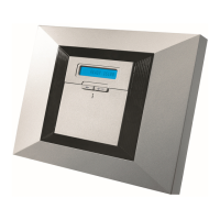
1
Battery
insertion
2
Battery connection
Figure 3.3 - Battery Insertion
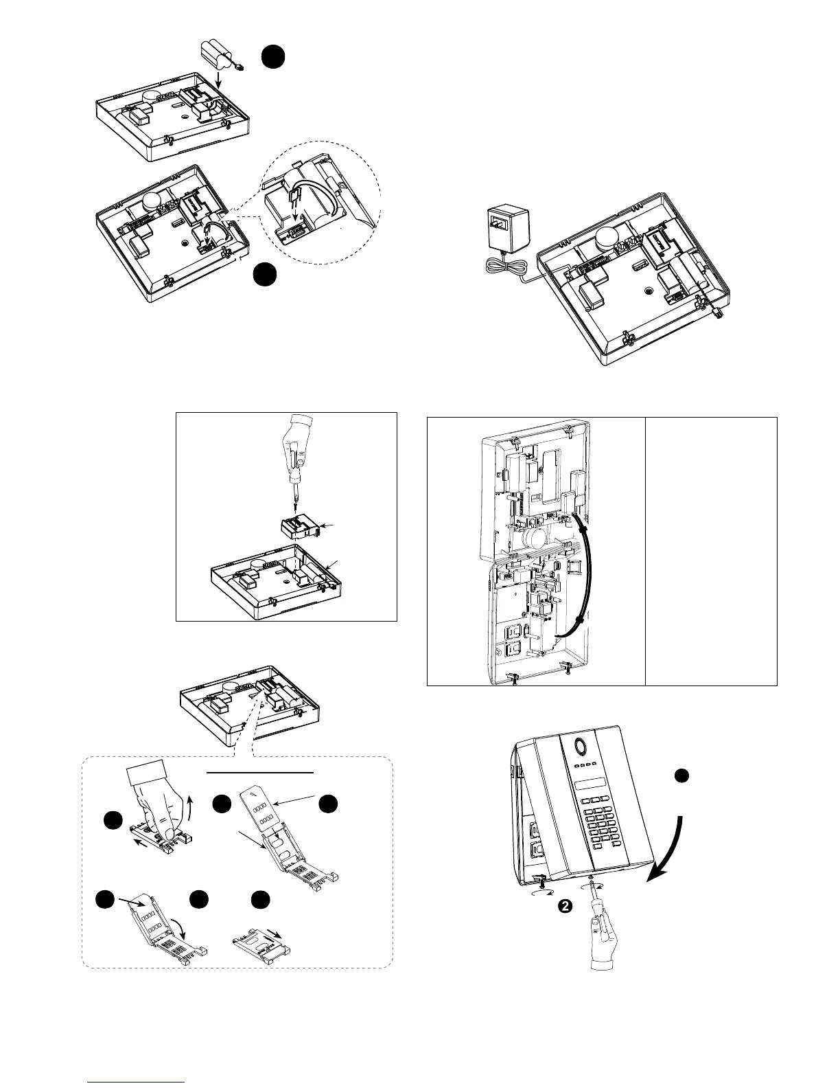
3.7 Optional GSM Module Mounting
Note: The GSM module is used with an internal antenna.
Optional external antenna can be used.
Caution: Do not install or remove the GSM module when
the system is powered by AC power or backup battery.
1. Plug in the
GSM Module
and fasten it
as follows:
Figure 3.4 - Optional GSM Module Mounting
2. Insert the SIM card into the GSM module
SIM card insertion
2
Open
cover
Align SIM
card in cover
(note cover
orientation)
3
Lock cover
to close
6
IMPORTANT
Do not insert or remove
SIM card when the
control panel is powered
by AC power or battery.
4
Slide SIM
card into
cover
5
Rotate cover
to close
1
Slide top
cover
Figure 3.5 - SIM Card insertion
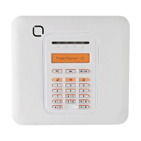
3.8 Power Cable Connection
External power connections (Option)
Connect the power cable and close the control panel as
shown below. Electrical socket-outlet shall be installed
near the equipment and shall be easily accessible.
WARNING! DO NOT USE AN OUTLET CONTROLLED
BY A WALL SWITCH.
Note: This equipment should be installed in accordance with
Chapter 2 of the National Fire Alarm Code, ANSI/NFPA 72,
(National Fire Protection Association).
Connect the power
adapter to the
power connector.
Fig. 3.6a - Power Cable Connection
Internal Power Connection (Option)
Fig. 3.6b
Internal Power
Cable Connection
.
3.9 Control Panel Final Closure
Control panel final closure is shown below.
Fasten
screws
1
Close
front
cover
Figure 3.7 - Final Closure
.

 Loading...